
Page 302 - Fluid Mechanics and Thermodynamics of Turbomachinery
P. 302
Hydraulic Turbines 283
U w 1 Direction of
blade motion
c 1 b
Nozzle 2
w 2
c 2
U
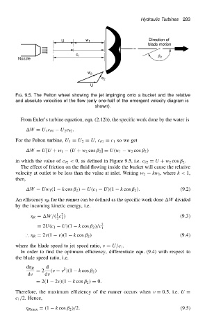
FIG. 9.5. The Pelton wheel showing the jet impinging onto a bucket and the relative
and absolute velocities of the flow (only one-half of the emergent velocity diagram is
shown).
From Euler’s turbine equation, eqn. (2.12b), the specific work done by the water is
U 2 c 2 .
W D U 1 c 1
For the Pelton turbine, U 1 D U 2 D U, c 1 D c 1 so we get
w 2 cos ˇ 2 /
W D U[U C w 1 .U C w 2 cos ˇ 2 ] D U.w 1
in which the value of c 2 < 0, as defined in Figure 9.5, i.e. c 2 D U C w 2 cos ˇ 2 .
The effect of friction on the fluid flowing inside the bucket will cause the relative
velocity at outlet to be less than the value at inlet. Writing w 2 D kw 1 , where k< 1,
then,
W D Uw 1 .1 k cos ˇ 2 / D U.c 1 U/.1 k cos ˇ 2 /. (9.2)
An efficiency R for the runner can be defined as the specific work done W divided
by the incoming kinetic energy, i.e.
1 2
R D W/. c / .9.3/
2 1
D 2U.c 1 U/.1 k cos ˇ 2 //c 1 2
∴ R D 2 .1 /.1 k cos ˇ 2 / .9.4/
where the blade speed to jet speed ratio, D U/c 1 .
In order to find the optimum efficiency, differentiate eqn. (9.4) with respect to
the blade speed ratio, i.e.
d R d 2
D 2 . /.1 k cos ˇ 2 /
d d
D 2.1 2 /.1 k cos ˇ 2 / D 0.
Therefore, the maximum efficiency of the runner occurs when D 0.5, i.e. U D
c 1 /2. Hence,
R max D .1 k cos ˇ 2 //2. (9.5)