Page 304 - Fluid Mechanics and Thermodynamics of Turbomachinery
P. 304

Hydraulic Turbines  285

                                                                       Surge tank
                                   Reservoir


                                                                     Penstock head


                                                                        Penstock
                               Z R


                                                                                 Pelton wheel


                                                                           Nozzle
                                                                                        Z N
                                                  Datum level
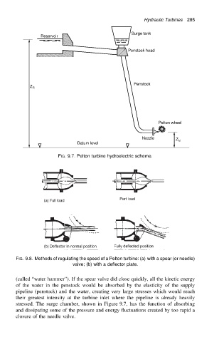
                                          FIG. 9.7. Pelton turbine hydroelectric scheme.


                          FIG. 9.8. Methods of regulating the speed of a Pelton turbine: (a) with a spear (or needle)
                                                valve; (b) with a deflector plate.

                          (called “water hammer”). If the spear valve did close quickly, all the kinetic energy
                          of the water in the penstock would be absorbed by the elasticity of the supply
                          pipeline (penstock) and the water, creating very large stresses which would reach
                          their greatest intensity at the turbine inlet where the pipeline is already heavily
                          stressed. The surge chamber, shown in Figure 9.7, has the function of absorbing
                          and dissipating some of the pressure and energy fluctuations created by too rapid a
                          closure of the needle valve.
   299   300   301   302   303   304   305   306   307   308   309