Page 308 - Fluid Mechanics and Thermodynamics of Turbomachinery
P. 308

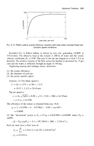
Hydraulic Turbines  289
                                         100


                                         h 0 , percent


                                            0                                100
                                                       Load ratio, per cent

                          FIG. 9.10. Pelton turbine overall efficiency variation with load under constant head and
                                                  constant speed conditions.

                            EXAMPLE 9.2. A Pelton turbine is driven by two jets, generating 4.0 MW at
                          375 rev/min. The effective head at the nozzles is 200 m of water and the nozzle
                          velocity coefficient, K N D 0.98. The axes of the jets are tangent to a circle 1.5 m in
                          diameter. The relative velocity of the flow across the buckets is decreased by 15 per
                          cent and the water is deflected through an angle of 165 deg.
                            Neglecting bearing and windage losses, determine:
                          (1) the runner efficiency;
                          (2) the diameter of each jet;
                          (3) the power specific speed.

                            Solution. (1) The blade speed is:
                              U D r D .375 ð  /30/ ð 1.5/2
                                D 39.27 ð 1.5/2 D 29.45 m/s.
                            The jet speed is:
                                      p               p
                                        2gHe D 0.98 ð   .2 ð 9.81 ð 200/ D 61.39 m/s
                               c 1 D K N
                              ∴   D U/c 1 D 0.4798.
                          The efficiency of the runner is obtained from eqn. (9.4):
                                                                          °
                                R D 2 ð 0.4798 ð .1  0.4798/.1  0.85 ð cos 165 /
                                 D 0.9090.
                          (2) The “theoretical” power is P th D P/  R D 4.0/0.909 D 4.40 MW where P th D
                           gQH e
                                                                              3
                                                        6
                              ∴ Q D P th /. gH e / D 4.4 ð 10 /.9810 ð 200/ D 2.243 m /s.
                          Each jet must have a flow area of,
                                     Q                               2
                                A j D   D 2.243/.2 ð 61.39/ D 0.01827 m .
                                     2c 1
                              ∴ d j D 0.1525 m.
   303   304   305   306   307   308   309   310   311   312   313