
Page 310 - Fluid Mechanics and Thermodynamics of Turbomachinery
P. 310
Hydraulic Turbines 291
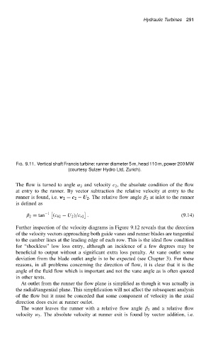
FIG. 9.11. Vertical shaft Francis turbine: runner diameter 5 m, head 110 m, power 200 MW
(courtesy Sulzer Hydro Ltd, Zurich).
The flow is turned to angle ˛ 2 and velocity c 2 , the absolute condition of the flow
at entry to the runner. By vector subtraction the relative velocity at entry to the
runner is found, i.e. w 2 D c 2 U 2 . The relative flow angle ˇ 2 at inlet to the runner
is defined as
1
ˇ 2 D tan .c 2 U 2 //c r2 . (9.14)
Further inspection of the velocity diagrams in Figure 9.12 reveals that the direction
of the velocity vectors approaching both guide vanes and runner blades are tangential
to the camber lines at the leading edge of each row. This is the ideal flow condition
for “shockless” low loss entry, although an incidence of a few degrees may be
beneficial to output without a significant extra loss penalty. At vane outlet some
deviation from the blade outlet angle is to be expected (see Chapter 3). For these
reasons, in all problems concerning the direction of flow, it is clear that it is the
angle of the fluid flow which is important and not the vane angle as is often quoted
in other texts.
At outlet from the runner the flow plane is simplified as though it was actually in
the radial/tangential plane. This simplification will not affect the subsequent analysis
of the flow but it must be conceded that some component of velocity in the axial
direction does exist at runner outlet.
The water leaves the runner with a relative flow angle ˇ 3 and a relative flow
velocity w 3 . The absolute velocity at runner exit is found by vector addition, i.e.