
Page 311 - Fluid Mechanics and Thermodynamics of Turbomachinery
P. 311
292 Fluid Mechanics, Thermodynamics of Turbomachinery
U 2
b 2
W
C 2 2
b 3 r 2 r 1
C 3
W 3
U 3 r 3
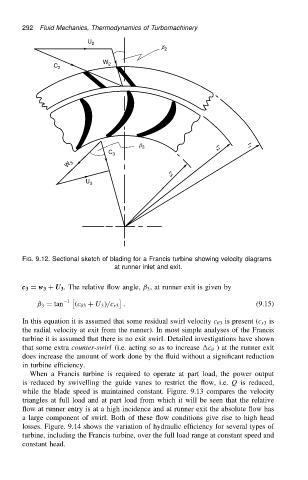
FIG. 9.12. Sectional sketch of blading for a Francis turbine showing velocity diagrams
at runner inlet and exit.
c 3 D w 3 C U 3 . The relative flow angle, ˇ 3 , at runner exit is given by
1
ˇ 3 D tan .c 3 C U 3 //c r3 . (9.15)
In this equation it is assumed that some residual swirl velocity c 3 is present (c r3 is
the radial velocity at exit from the runner). In most simple analyses of the Francis
turbine it is assumed that there is no exit swirl. Detailed investigations have shown
that some extra counter-swirl (i.e. acting so as to increase c ) at the runner exit
does increase the amount of work done by the fluid without a significant reduction
in turbine efficiency.
When a Francis turbine is required to operate at part load, the power output
is reduced by swivelling the guide vanes to restrict the flow, i.e. Q is reduced,
while the blade speed is maintained constant. Figure. 9.13 compares the velocity
triangles at full load and at part load from which it will be seen that the relative
flow at runner entry is at a high incidence and at runner exit the absolute flow has
a large component of swirl. Both of these flow conditions give rise to high head
losses. Figure. 9.14 shows the variation of hydraulic efficiency for several types of
turbine, including the Francis turbine, over the full load range at constant speed and
constant head.