
Page 316 - Fluid Mechanics and Thermodynamics of Turbomachinery
P. 316
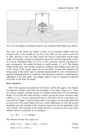
Hydraulic Turbines  297


                          FIG. 9.16. Part section of a Kaplan turbine in situ (courtesy Sulzer Hydro Ltd, Zurich).

                          The vanes of the runner are similar to those of an axial-flow turbine rotor but
                          designed with a twist suitable for the free-vortex flow at entry and an axial flow
                          at outlet. Because of the very high torque that must be transmitted and the large
                          length of the blades, strength considerations impose the need for large blade chords.
                          As a result, pitch/chord ratios of 1.0 to 1.5 are commonly used by manufacturers
                          and, consequently, the number of blades is small, usually 4, 5 or 6. The Kaplan
                          turbine incorporates one essential feature not found in other turbine rotors and that
                          is the setting of the stagger angle can be controlled. At part load operation the
                          setting angle of the runner vanes is adjusted automatically by a servo mechanism to
                          maintain optimum efficiency conditions. This adjustment requires a complementary
                          adjustment of the inlet guide vane stagger angle in order to maintain an absolute
                          axial flow at exit from the runner.
                          Basic equations

                            Most of the equations presented for the Francis turbine also apply to the Kaplan
                          (or propeller) turbine, apart from the treatment of the runner. Figure 9.17 shows
                          the velocity triangles and part section of a Kaplan turbine drawn for the mid-blade
                          height. At exit from the runner the flow is shown leaving the runner without a whirl
                          velocity, i.e. c  3 D 0 and constant axial velocity. The theory of free-vortex flows was
                          expounded in Chapter 6 and the main results as they apply to an incompressible fluid
                          are given here. The runner blades will have a fairly high degree of twist, the amount
                          depending upon the strength of the circulation function K and the magnitude of the
                          axial velocity. Just upstream of the runner the flow is assumed to be a free-vortex
                          and the velocity components are accordingly:

                              c  2 D K/r  c x D a constant.

                          The relations for the flow angles are
                                                           K/.rc x /                     .9.22a/
                              tan ˇ 2 D U/c x  tan ˛ 2 D r/c x
                              tan ˇ 3 D U/c x D r/c x .                                 .9.22b/