Page 317 - Fluid Mechanics and Thermodynamics of Turbomachinery
P. 317

298 Fluid Mechanics, Thermodynamics of Turbomachinery
                                                                             U
                                         r 1                       b
                                                                    2
                                                                                  a 2
                                      1
                                                                      W 2      c 2


                                  2
                                                                                  Blade motion

                                  3                                               b 3

                                                                           c  = c x    W 3
                                                                            3

                                       Exit                                           U
                                       flow
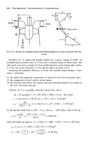
                          FIG. 9.17. Section of a Kaplan turbine and velocity diagrams at inlet to and exit from the
                                                          runner.


                            EXAMPLE 9.4. A small-scale Kaplan turbine has a power output of 8 MW, an
                          available head at turbine entry of 13.4 m and a rotational speed of 200 rev/min. The
                          inlet guide vanes have a length of 1.6 m and the diameter at the trailing edge surface
                          is 3.1 m. The runner diameter is 2.9 m and the hub to tip ratio is 0.4.
                            Assuming the hydraulic efficiency is 92 per cent and the runner design is “free-
                          vortex”, determine:

                          (1) the radial and tangential components of velocity at exit from the guide vanes;
                          (2) the component of axial velocity at the runner;
                          (3) the absolute and relative flow angles upstream and downstream of the runner at
                             the hub, mid-radius and tip.

                            Solution.As P D   H  gQH E , then the volume flow rate is
                                                        6
                                 Q D P/.  H  gH E / D 8 ð 10 /.0.92 ð 9810 ð 13.4/ D 66.15 m/s 2
                              ∴ c r1 D Q/.2 r 1 L/ D 66.15/.2  ð 1.55 ð 1.6/ D 4.245 m/s 2
                                         4Q                        2                   2
                                c x2 D  2        D 4 ð 66.15/.  ð 2.9 ð 0.84/ D 11.922 m/s .
                                              2
                                      D .1     /
                                        2t
                          As the specific work done is W D U 2 c  2 and   H D W/.gH E /, then at the tip
                                             0.92 ð 9.81 ð 13.4
                                     H gH E
                              c  2 D      D                  D 3.892 m/s,
                                     U 2          30.37
                          where the blade tip speed is, U 2 D D 2 /2 D .200 ð  /30/ ð 2.9/2 D 30.37 m/s

                              c  1 D c  2 r 2 /r 1 D 3.892 ð 1.45/1.55 D 3.725 m/s 2
                                                       3.725
                              ˛ 1 D tan  1  c  1  D tan  1    D 41.26 deg .
                                          c r1         4.245
   312   313   314   315   316   317   318   319   320   321   322