
Page 318 - Fluid Mechanics and Thermodynamics of Turbomachinery
P. 318
Hydraulic Turbines 299
TABLE 9.4. Calculated values of flow angles for
Example 9.4.
Ratio r/r t
Parameter 0.4 0.7 1.0
c 2 m/s 9.955 5.687 3.982
tan ˛ 2 0.835 0.4772 0.334
˛ 2 (deg) 39.86 25.51 18.47
U/c x2 1.019 1.7832 2.547
ˇ 2 (deg) 10.43 52.56 65.69
ˇ 3 (deg) 45.54 60.72 68.57
80
b 3 b
Flow angle, deg 40 2 a 2
0
0.4 0.6 0.8 1.0
Radius ratio, r/r
t
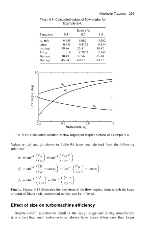
FIG. 9.18. Calculated variation of flow angles for Kaplan turbine of Example 9.4.
Values ˛ 2 , ˇ 2 and ˇ 3 shown in Table 9.4 have been derived from the following
relations:
˛ 2 D tan 1 c 2 D tan 1 c 2t r t
c x2 c x2 r
r U 2t r
1 1
ˇ 2 D tan tan ˛ 2 D tan tan ˛ 2
c x2 c x2 r t
U 1 U 2t r
1
ˇ 3 D tan D tan .
c x2 c x2 r t
Finally, Figure 9.18 illustrates the variation of the flow angles, from which the large
amount of blade twist mentioned earlier can be inferred.
Effect of size on turbomachine efficiency
Despite careful attention to detail at the design stage and during manufacture
it is a fact that small turbomachines always have lower efficiencies than larger