
Page 313 - Fluid Mechanics and Thermodynamics of Turbomachinery
P. 313
294 Fluid Mechanics, Thermodynamics of Turbomachinery
Basic equations
Euler’s turbine equation, eqn. (2.12b), in the present notation, is written as
W D U 2 c 2 U 3 c 3 . (9.16)
If the flow at runner exit is without swirl then the equation reduces to
W D U 2 c 2 . (9.16a)
The effective head for all reaction turbines, H E , is the total head available at the
turbine inlet relative to the surface of the tailrace. At entry to the runner the energy
available is equal to the sum of the kinetic, potential and pressure energies, i.e.
p 2 p a 1 2
H N / D C c C gz 2 , (9.17)
g.H E 2 2
where H N is the loss of head due to friction in the volute and guide vanes and
p 2 is the absolute static pressure at inlet to the runner.
At runner outlet the energy in the water is further reduced by the amount of
specific work W and by friction work in the runner, gH R and this remaining
energy equals the sum of the pressure potential and kinetic energies, i.e.
1 2
g.H E H N H R / W D c C p 3 / p a / C gz 3 (9.18)
2 3
where p 3 is the absolute static pressure at runner exit.
By differencing eqns. (9.17) and (9.18), the specific work is obtained
p 03 // z 3 / (9.19)
W D .p 02 gH R C g.z 2
where p 02 and p 03 are the absolute total pressures at runner inlet and exit.
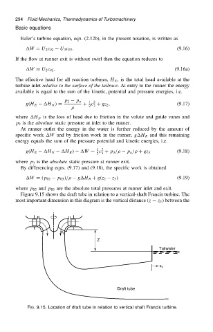
Figure 9.15 shows the draft tube in relation to a vertical-shaft Francis turbine. The
most important dimension in this diagram is the vertical distance .z D z 3 / between the
c 3
Z
Tailwater
c 4
Draft tube
FIG. 9.15. Location of draft tube in relation to vertical shaft Francis turbine.