
Page 303 - Fluid Mechanics and Thermodynamics of Turbomachinery
P. 303
284 Fluid Mechanics, Thermodynamics of Turbomachinery
1.0
k = 1.0
0.9 0.8
Efficiency of runner
0
0.2 0.4 0.6 0.8 1.0
Blade speed/jet speed ratio, n
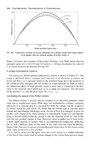
FIG. 9.6. Theoretical variation of runner efficiency for a Pelton wheel with blade speed
to jet speed ratio for several values of friction factor k.
Figure. 9.6 shows the variation of the runner efficiency with blade speed ratio for
assumed values of k D 0.8, 0.9 and 1.0 with ˇ 2 D 165 deg. In practice the value of
k is usually found to be between 0.8 and 0.9.
A simple hydroelectric scheme
The layout of a Pelton turbine hydroelectric scheme is shown in Figure 9.7. The
water is delivered from a constant level reservoir at an elevation z R (above sea
level) and flows via a pressure tunnel to the penstock head, down the penstock to
the turbine nozzles emerging onto the buckets as a high speed jet. In order to reduce
the deleterious effects of large pressure surges, a surge tank is connected to the flow
close to the penstock head which acts so as to damp out transients. The elevation
of the nozzles is z N and the gross head, H G D z R z N .
Controlling the speed of the Pelton turbine
The Pelton turbine is usually directly coupled to an electrical generator which
must run at synchronous speed. With large size hydroelectric schemes supplying
electricity to a national grid it is essential for both the voltage and the frequency
to closely match the grid values. To ensure that the turbine runs at constant speed
despite any load changes which may occur, the rate of flow Q is changed. A spear (or
needle) valve, Figure 9.8a, whose position is controlled by means of a servomecha-
nism, is moved axially within the nozzle to alter the diameter of the jet. This works
well for very gradual changes in load. However, when a sudden loss in load occurs
a more rapid response is needed. This is accomplished by temporarily deflecting
the jet with a deflector plate so that some of the water does not reach the buckets,
Figure 9.8b. This acts to prevent overspeeding and allows time for the slower acting
spear valve to move to a new position.
It is vital to ensure that the spear valve does move slowly as a sudden reduction
in the rate of flow could result in serious damage to the system from pressure surges