
Page 82 - Fluid Mechanics and Thermodynamics of Turbomachinery
P. 82
Two-dimensional Cascades 63
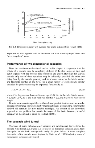
FIG. 3.6. Efficiency variation with average flow angle (adapted from Howell 1945).
experimental data together with an allowance for wall boundary-layer losses and
“secondary-flow” losses.
Performance of two-dimensional cascades
From the relationships developed earlier in this chapter it is apparent that the
effects of a cascade may be completely deduced if the flow angles at inlet and
outlet together with the pressure loss coefficient are known. However, for a given
cascade only one of these quantities may be arbitrarily specified, the other two
being fixed by the cascade geometry and, to a lesser extent, by the Mach number
and Reynolds number of the flow. For a given family of geometrically similar
cascades the performance may be expressed functionally as,
, a 2 D .a 1 ,M 1 , Re/, (3.28)
where is the pressure loss coefficient, eqn. (3.7), M 1 is the inlet Mach number
= c 1 /.
RT 1 / 1/2 , Re is the inlet Reynolds number = 1 c 1 l/ based on blade chord
length.
Despite numerous attempts it has not been found possible to determine, accurately,
cascade performance characteristics by theoretical means alone and the experimental
method still remains the most reliable technique. An account of the theoretical
approach to the problem lies outside the scope of this book, however, a useful
summary of the subject is given by Horlock (1958).
The cascade wind tunnel
The basis of much turbomachinery research and development derives from the
cascade wind tunnel, e.g. Figure 3.1 (or one of its numerous variants), and a brief
description of the basic aerodynamic design is given below. A more complete
description of the cascade tunnel is given by Carter et al. (1950) including many of
the research techniques developed.