
Page 84 - Fluid Mechanics and Thermodynamics of Turbomachinery
P. 84
Two-dimensional Cascades 65
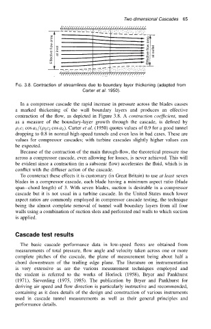
FIG. 3.8. Contraction of streamlines due to boundary layer thickening (adapted from
Carter et al. 1950).
In a compressor cascade the rapid increase in pressure across the blades causes
a marked thickening of the wall boundary layers and produces an effective
contraction of the flow, as depicted in Figure 3.8. A contraction coefficient, used
as a measure of the boundary-layer growth through the cascade, is defined by
1 c 1 cos a 1 /. 2 c 2 cos a 2 /. Carter et al. (1950) quotes values of 0.9 for a good tunnel
dropping to 0.8 in normal high-speed tunnels and even less in bad cases. These are
values for compressor cascades; with turbine cascades slightly higher values can
be expected.
Because of the contraction of the main through-flow, the theoretical pressure rise
across a compressor cascade, even allowing for losses, is never achieved. This will
be evident since a contraction (in a subsonic flow) accelerates the fluid, which is in
conflict with the diffuser action of the cascade.
To counteract these effects it is customary (in Great Britain) to use at least seven
blades in a compressor cascade, each blade having a minimum aspect ratio (blade
span chord length) of 3. With seven blades, suction is desirable in a compressor
cascade but it is not usual in a turbine cascade. In the United States much lower
aspect ratios are commonly employed in compressor cascade testing, the technique
being the almost complete removal of tunnel wall boundary layers from all four
walls using a combination of suction slots and perforated end walls to which suction
is applied.
Cascade test results
The basic cascade performance data in low-speed flows are obtained from
measurements of total pressure, flow angle and velocity taken across one or more
complete pitches of the cascade, the plane of measurement being about half a
chord downstream of the trailing edge plane. The literature on instrumentation
is very extensive as are the various measurement techniques employed and
the student is referred to the works of Horlock (1958), Bryer and Pankhurst
(1971), Sieverding (1975, 1985). The publication by Bryer and Pankhurst for
deriving air speed and flow direction is particularly instructive and recommended,
containing as it does details of the design and construction of various instruments
used in cascade tunnel measurements as well as their general principles and
performance details.