
Page 86 - Fluid Mechanics and Thermodynamics of Turbomachinery
P. 86
Two-dimensional Cascades 67
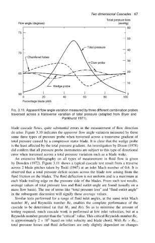
FIG. 3.10. Apparent flow angle variation measured by three different combination probes
traversed across a transverse variation of total pressure (adapted from Bryer and
Pankhurst 1971).
blade cascade flows, quite substantial errors in the measurement of flow direction
do arise. Figure 3.10 indicates the apparent flow angle variation measured by these
same three types of pressure probe when traversed across a transverse gradient of
total pressure caused by a compressor stator blade. It is clear that the wedge probe
is the least affected by the total pressure gradient. An investigation by Dixon (1978)
did confirm that all pressure probe instruments are subject to this type of directional
error when traversed across a total pressure variation such as a blade wake.
An extensive bibliography on all types of measurement in fluid flow is given
by Dowden (1972). Figure 3.11 shows a typical cascade test result from a traverse
across 2 blade pitches taken by Todd (1947) at an inlet Mach number of 0.6. It is
observed that a total pressure deficit occurs across the blade row arising from the
fluid friction on the blades. The fluid deflection is not uniform and is a maximum at
each blade trailing edge on the pressure side of the blades. From such test results,
average values of total pressure loss and fluid outlet angle are found (usually on a
mass flow basis). The use of terms like “total pressure loss” and “fluid outlet angle”
in the subsequent discussion will signify these average values.
Similar tests performed for a range of fluid inlet angles, at the same inlet Mach
number M 1 and Reynolds number Re, enables the complete performance of the
cascade to be determined (at that M 1 and Re). So as to minimise the amount of
testing required, much cascade work is performed at low inlet velocities, but at a
Reynolds number greater than the “critical” value. This critical Reynolds number Re c
5
is approximately 2 ð 10 based on inlet velocity and blade chord. With Re>Re c ,
total pressure losses and fluid deflections are only slightly dependent on changes