
Page 100 - Fluid Power Engineering
P. 100
74 Cha pte r T h ree
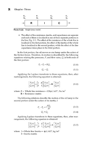
FIGURE 3.11 Single-lump model.
• The effect of line resistance, inertia, and capacitance are separate
and each of them is localized in one of three separate portions in
the line, Fig. 3.11. The effect of the resistance of the whole line is
localized in the first portion, the effect of the inertia of the whole
line is localized in the second portion, while the effect of the line
capacitance takes place in the third portion.
In the first portion, the oil moves as one lump under the action of
the friction forces. Therefore, its motion is described by the following
equations relating the pressures, P, and flow rates, Q, at both ends of
the first portion:
P − P = RQ 1 (3.10)
1
o
Q = Q 1 (3.11)
o
Applying the Laplace transform to these equations, then, after
rearrangement, the following equation is obtained:
⎤⎡
⎡ Ps ()⎤ ⎡1 R Ps ()⎤ ⎡ Ps ()⎤
⎢ o ⎥ = ⎢ ⎥⎢ 1 ⎥ = R ⎢ 1 ⎥ (3.12)
⎣ Qs () ⎦ ⎣ 0 1 ⎦⎣ Qs () ⎦ ⎣ Qs () ⎦
1
1
o
4
where R = Whole line resistance = 128μL/ πD , Ns/m 5
R = Resistance matrix
The following relations describe the motion of the oil lump in the
second portion under the action of its inertia, I:
dQ
P − P = I 2 (3.13)
1 2 dt
Q = Q 2 (3.14)
1
Applying Laplace transform to these equations, then, after rear-
rangement, the following equation is obtained:
⎡ Ps ()⎤ 1 ⎡ Is Ps ()⎤ ⎡ Ps ()⎤
⎤⎡
2
2
⎢ Qs () ⎥ = ⎢ ⎥⎢ Qs () ⎥ ⎥ = I ⎢ Qs () ⎥ (3.15)
1
⎣ 1 ⎦ ⎣ 0 1 ⎦⎣ 2 ⎦ ⎣ 2 ⎦
2
where I = Whole line Inertia = 4ρL/ πD , kg/m 4
I = Inertia matrix