Page 101 - Fluid Power Engineering
P. 101

Hydraulic Transmission Lines     75


                   Considering the effect of oil compressibility in the last portion,
               the following relations can be deduced:

                                              dP
                                    Q − Q =  C  L                   (3.16)
                                      2  L
                                               dt
                                        P =  P
                                           2  L                     (3.17)
                   Applying Laplace transform to these equations, then, after rear-
               rangement, the following equation is obtained:
                            ⎡ Ps ()⎤  ⎡  1  0⎤⎡  Ps ()⎤  ⎡ Ps ()⎤
                                            L
                                                      L
                              2
                            ⎢ Qs () ⎥  =  ⎢ Cs 1 ⎥⎢ Qs () ⎥ ⎥  = C  ⎢ Qs () ⎥  (3.18)
                            ⎣  2  ⎦  ⎣   ⎦⎣  L  ⎦     ⎣  L  ⎦
                                                 2
               where  C = Whole line capacitance =  πDL 4/  B,  m /Pa
                                                         3
                     C = Capacitance matrix
                   The transfer matrix relating the line parameters P , Q , P , and Q  can be
                                                        o  o  L    L
               deduced by eliminating the assumed internal variables, P , P , Q , and Q .
                                                           1  2  1     2
                             ⎡ Ps()⎤  ⎡ Ps ()⎤   ⎡ Ps ()⎤     ⎡ Ps ()⎤
                             ⎢  o  ⎥  = R  ⎢  1  ⎥   = RI  ⎢  2  ⎥  = RIC  ⎢  L  ⎥
                             ⎣ Qs() ⎦  ⎣ Qs () ⎦  ⎣ Qs () ⎦   ⎣ Qs () ⎦
                               o
                                                   2
                                        1
                                                                L
               or
                           ⎡ Ps ()⎤  ⎡ ICs +  RCs + 1  Is R P (s)⎡  s ⎤
                                                  + ⎤
                                     2
                                                       L
                           ⎢ Qs () ⎥ =  ⎢  Cs     1  ⎥⎢ Qs () ⎥     (3.19)
                            o
                           ⎣  o  ⎦  ⎣               ⎦⎣  L  ⎦
                   This equation defines the relation between the pressures and flow
               rates at both of the line extremities in the transient conditions, assum-
               ing a single oil lump.
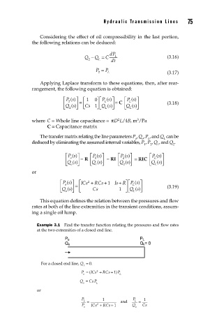
                 Example 3.1  Find the transfer function relating the pressures and flow rates
                 at the two extremities of a closed end line.


                   For a closed end line, Q  = 0.
                                    L
                                   P = ( ICs +  RCs + )1  P
                                         2
                                    o             L
                                  Q =  CsP
                                   o     L
                 or
                                   P       1           P   1
                                    L  =          and   L  =
                                         2
                                   P o  ICs +  RCs + 1    Q o  Cs
   96   97   98   99   100   101   102   103   104   105   106