
Page 96 - Fluid Power Engineering
P. 96
Hydraulic Transmission Lines 71
(a)
(b)
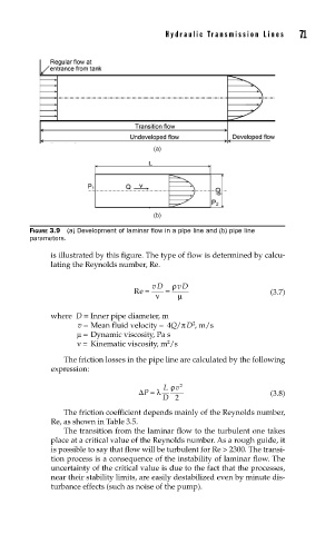
FIGURE 3.9 (a) Development of laminar fl ow in a pipe line and (b) pipe line
parameters.
is illustrated by this figure. The type of flow is determined by calcu-
lating the Reynolds number, Re.
Re = vD = ρ vD (3.7)
ν
μ
where D = Inner pipe diameter, m
v = Mean fluid velocity = 4Q/π D , m/s
2
μ = Dynamic viscosity, Pa s
2
ν = Kinematic viscosity, m /s
The friction losses in the pipe line are calculated by the following
expression:
L ρ v 2
ΔP =λ (3.8)
D 2
The friction coefficient depends mainly of the Reynolds number,
Re, as shown in Table 3.5.
The transition from the laminar flow to the turbulent one takes
place at a critical value of the Reynolds number. As a rough guide, it
is possible to say that flow will be turbulent for Re > 2300. The transi-
tion process is a consequence of the instability of laminar flow. The
uncertainty of the critical value is due to the fact that the processes,
near their stability limits, are easily destabilized even by minute dis-
turbance effects (such as noise of the pump).