
Page 94 - Fluid Power Engineering
P. 94
Hydraulic Transmission Lines 69
where v = Fluid velocity, m/s
ΔP = Pressure losses, Pa
ξ = Local loss coefficient
ρ = Fluid density, kg/m 3
In laminar flow, the effects of local disturbances are usually insig-
nificant compared with the friction losses. In the case of turbulent
flow, the local loss coefficient is determined almost exclusively by the
geometry of the local feature. It changes very little with the Reynolds
number. The following are some of the local features existing in the
hydraulic systems:
• Channel expansion, gradual or abrupt
• Channel contraction, gradual or abrupt
• Channel bend, smooth or sharp (elbow)
• Branching junctions
• Control valves
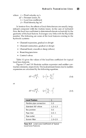
Table 3.3 gives the values of the local loss coefficient for typical
local loss elements.
Figures 3.7 and 3.8 illustrate sudden expansion and sudden con-
traction elements, respectively. The local pressure losses due to sudden
expansion are calculated by the following equation:
ρ v 2 ⎛ A ⎞ 2
ΔP = ξ 1 , ξ = 1 − 1 ⎟ (3.4)
⎜
2 ⎝ A ⎠
2
or
ρ v 2 ⎛ A ⎞ 2
ΔP = ξ 2 , ξ = ⎜ 2 − 1 ⎟ (3.5)
2 ⎝ A ⎠
1
Local Feature ξ
Flexible pipe connection 0.3
o
Standard 90 elbow 1.2–1.3
Tee junction 3.5
Pipe inlet 0.5–1
Pipe outlet 1
Screen filter 1.5–2.5
TABLE 3.3 Local Loss Coefficient of Typical
Local Loss Features