
Page 93 - Fluid Power Engineering
P. 93
68 Cha pte r T h ree
6. Secure for protection.
Install hose runs to avoid rubbing or
abrasion. Use hose clamps to support
long runs of hose or to keep hose away
from moving parts. It is important that
the clamps not allow the hose to move
in order to avoid abrasion and premature
hose failure.
7. Avoid improper hose movement.
Make sure the relative motion of the
machine components produces bending
rather than twisting of the hose. Hose
should be routed so the flex is in the
same plane as the equipment movement.
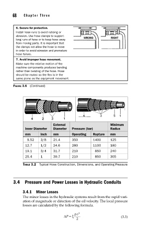
FIGURE 3.6 (Continued)
External Minimum
Inner Diameter Diameter Pressure (bar) Radius
mm inch mm Operating Rupture mm
9.52 3/8 21.4 350 1400 125
12.7 1/2 24.6 280 1100 180
19.1 3/4 31.7 210 850 240
25.4 1 39.7 210 850 305
TABLE 3.2 Typical Hose Construction, Dimensions, and Operating Pressure
3.4 Pressure and Power Losses in Hydraulic Conduits
3.4.1 Minor Losses
The minor losses in the hydraulic systems result from the rapid vari-
ation of magnitude or direction of the oil velocity. The local pressure
losses are calculated by the following formula.
ρ v 2
ΔP =ξ (3.3)
2