
Page 135 - Fluid Power Engineering
P. 135
Hydraulic Pumps 109
via a groove in the cam surface to the bore of the piston into the
pumping chamber.
Phase 3: The piston is at the lower dead point. The pumping
chamber is completely filled (maximum volume). The suction valve
and exit check valve are closed.
Phase 4: As the cam rotates, the piston is moved outwards in the
radial direction. The fluid is com pressed in the displacement chamber.
The increased fluid pressure opens the exit check valve, and the fluid
flows into the ring chan nel (13), which connects the pumping elements.
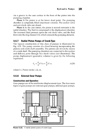
4.6.7 Radial Piston Pumps of Crank Type
The typical construction of this class of pumps is illustrated by
Fig. 4.21. The pump consists of a fixed housing incorporating the
pistons and crank shaft assembly. The pistons are driven by means
of a crank shaft. The pumping chambers are connected to the suction
and delivery ports through two check valves (not illustrated). The
pump displacement (geometric volume) is given by the following
expression:
π π
2
2
V = d hz = d ez (4.29)
g 4 2
where h = Piston stroke = 2e, m.
4.6.8 External Gear Pumps
Construction and Operation
Gear pumps are of the multirotor displacement type. The four main
types of gear pumps are external gear pumps, internal gear pumps,
FIGURE 4.21 A radial piston pump of crank type.