
Page 138 - Fluid Power Engineering
P. 138
112 Cha pte r F o u r
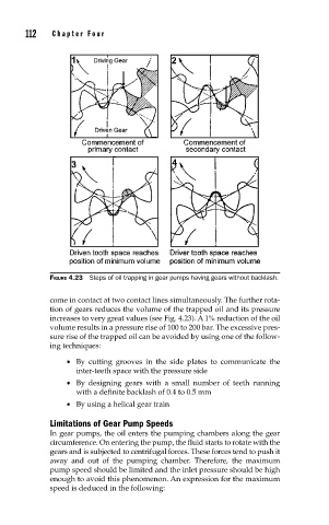
FIGURE 4.23 Steps of oil trapping in gear pumps having gears without backlash.
come in contact at two contact lines simultaneously. The further rota-
tion of gears reduces the volume of the trapped oil and its pressure
increases to very great values (see Fig. 4.23). A 1% reduction of the oil
volume results in a pressure rise of 100 to 200 bar. The excessive pres-
sure rise of the trapped oil can be avoided by using one of the follow-
ing techniques:
• By cutting grooves in the side plates to communicate the
inter-teeth space with the pressure side
• By designing gears with a small number of teeth running
with a definite backlash of 0.4 to 0.5 mm
• By using a helical gear train
Limitations of Gear Pump Speeds
In gear pumps, the oil enters the pumping chambers along the gear
circumference. On entering the pump, the fluid starts to rotate with the
gears and is subjected to centrifugal forces. These forces tend to push it
away and out of the pumping chamber. Therefore, the maximum
pump speed should be limited and the inlet pressure should be high
enough to avoid this phenomenon. An expression for the maximum
speed is deduced in the following: