
Page 141 - Fluid Power Engineering
P. 141
Hydraulic Pumps 115
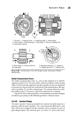
1. Housing, 1.1. Bearing cover, 1.2. Blanking plate, 2. Internal gear,
3. Pinion shaft, 4. Shaft bearings, 5. Side plates, 6. Stop pin, Sealing rolls,
9. Hydrostatic bearing
5. Wear plates, 8. Pressure field on 7. Segment assembly, 7.1. Segment,
the side plate 7.2. Segment carrier, 7.3. Sealing rolls
FIGURE 4.26 Construction of an internal gear pump. (Courtesy of Bosch
Rexroth AG.)
Radial Compensation Forces
The radial compensation force, F , acts on the segment (7.1) and the
R
segment carrier (7.2). The area ratios and the position of the sealing
rolls (7.3) between the segments and the segment carrier are designed
to provide an almost leak-free seal between the internal gear, the seg-
ment assembly (7), and the external gear. The spring elements under
the sealing rolls (7.3) ensure a sufficient contact force at startup.
Figure 4.27 shows the typical flow characteristics in modern designs
of internal gear pumps with different geometric volumes (sizes).
4.6.10 Gerotor Pumps
The term “gerotor” means generated rotor, and is the trade name for a
popular internal gear element. The cross-sectional illustration (see
Fig. 4.28) shows a typical Gerotor element, which consists of a pair of
gear-shaped parts. The internal gear (or rotor) (1), drives the outer