
Page 144 - Fluid Power Engineering
P. 144
118 Cha pte r F o u r
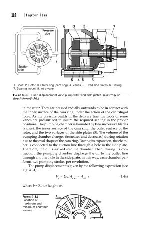
1. Shaft, 2. Rotor, 3. Stator ring (cam ring), 4. Vanes, 5. Fixed side plates, 6. Casing,
7. Bearing mount, 8. Intra-vane
FIGURE 4.30 Fixed displacement vane pump with fi xed side plates. (Courtesy of
Bosch Rexroth AG.)
in the rotor. They are pressed radially outwards to be in contact with
the inner surface of the cam ring under the action of the centrifugal
force. As the pressure builds in the delivery line, the roots of some
vanes are pressurized to insure the required sealing in the proper
positions. The pumping chamber is bounded by two successive blades
(vanes), the inner surface of the cam ring, the outer surface of the
rotor, and the two surfaces of the side plates (5). The volume of the
pumping chamber changes (increases and decreases) during rotation
due to the oval shape of the cam ring. During its expansion, the cham-
ber is connected to the suction line through a hole in the side plate.
Therefore, the oil is sucked into the chamber. Then, during its con-
traction, the pumping chamber displaces the oil to the outlet line
through another hole in the side plate. In this way, each chamber per-
forms two pumping strokes per revolution.
The pump displacement is given by the following expression (see
Fig. 4.31):
V = 2 bz A − A ) (4.44)
(
g max min
where b = Rotor height, m.
FIGURE 4.31
Location of
maximum and
minimum chamber
volume.