
Page 149 - Fluid Power Engineering
P. 149
Hydraulic Pumps 123
• Hydraulic servo controllers, for closed-loop control of the pump
displacement
• Electrohydraulic proportional controllers, for open-loop control
of the pump displacement
• Electrohydraulic servo controllers, for open- and closed-loop
control of the pump displacement
4.7.2 Pressure-Compensated Vane Pumps
Construction and Operation
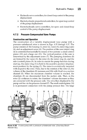
The construction of a variable displacement vane pump with a
pressure-unbalanced rotor is shown in Figs. 4.35 through 4.37. The
pump consists of: the housing (1), rotor (2), vanes (3), stator ring (cam)
(4), and an adjustment screw (6). The position of the cam (stator) ring
(4) is controlled horizontally by means of two pistons: a small control
piston (10) and a large one (11). The vertical position of the cam is
determined by the adjustment screw (7). The pumping chambers (8)
are formed by the vanes (3), the rotor (2), the stator ring (4), and the
side (control) plates (9). In order to ensure the pump function during
start-up, the stator ring (4) is held in the eccentric position (displace-
ment position) by the spring (5). The stator is eccentrically mounted
with respect to the rotor. Then, due to the rotation of the rotor (2), the
volume of the chambers (8) increases and fills with fluid via a suction
channel (S). When the maximum chamber volume is reached, the
chambers (8) are disconnected from the suction side. Then, as the
rotor (2) continues to rotate, the chambers’ volume decreases as they
are connected with the pressure side. The oil is then displaced to the
pump exit line via the pressure channel (P). The small control piston (10)
is in permanent connection with the pump pressure line. The large
FIGURE 4.35 A vane pump with a pressure unbalanced rotor. (Courtesy Bosch
Rexroth AG.)