
Page 154 - Fluid Power Engineering
P. 154
128 Cha pte r F o u r
• Point 2 can be displaced horizontally by means of the adjust-
ment spring setting, and displaced vertically by using the maxi-
mum inclination angle limiter.
• The slope of line 2–3 is imposed by the stiffness of the first
control spring, while that of line 3–4 is determined by the
summation of stiffness of both of the first and second control
springs.
• The operation in the vicinity of point 3 does not consume the
whole available power of the prime mover due to the straight
line approximation of the constant power curve. But the
simplicity and relative lower cost give good appreciation to
this design. However, other power controllers are commercially
available, which better agree with the constant power curve.
4.8 Rotodynamic Pumps
Rotodynamic pumps, such as centrifugal pumps, are machines that
transfer energy to the liquid by increasing its momentum. This class
of pumps is used widely wherever high flow rates are required under
low or medium heads. They offer advantages such as simple con-
struction, low price, easy maintenance and repair, and the ability to
work with liquids of low lubricity.
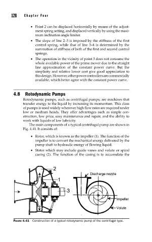
The main components of a typical centrifugal pump are shown in
Fig. 4.41. It consists of:
• Rotor, which is known as the impeller (1). The function of the
impeller is to convert the mechanical energy delivered by the
pump shaft to hydraulic energy of flowing liquid.
• Stator which may include guide vanes and volute or spiral
casing (2). The function of the casing is to accumulate the
FIGURE 4.41 Construction of a typical rotodynamic pump of the centrifugal type.