
Page 155 - Fluid Power Engineering
P. 155
Hydraulic Pumps 129
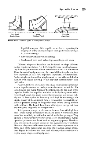
FIGURE 4.42 Impeller types of rotodynamic pumps.
liquid flowing out of the impeller, as well as recuperating the
major part of the kinetic energy of the liquid by converting it
to pressure energy.
• Drive shaft with convenient sealing.
• Mechanical parts such as bearings, couplings, and so on.
Different shapes of impellers can be found to adapt different
design requirements (see Fig. 4.42). Impellers are classified accord-
ing to the major direction of flow in reference to the axis of rotation.
Thus, the centrifugal pumps may have radial flow impellers, mixed
flow impellers, or axial flow impellers. Impellers are further classi-
fied as single suction with a single outlet on one side, and double
suction with liquid flowing to the impeller symmetrically from
both sides.
Figure 4.41 shows an example of a single-stage centrifugal pump.
As the impeller rotates, an underpressure is created at its inlet. The
liquid enters the pump through the inlet nozzle to the inlet of the
impeller. Inside the impeller, and due to the hydrodynamic effect
(centrifugal force), the liquid momentum increases as it moves radi-
ally out of the impeller to the casing with high kinetic energy. The
kinetic energy of the delivered flow is recuperated (converted) par-
tially as pressure energy in the guide vanes, volute casing, and the
outlet diffuser. The liquid then flows with higher energy out from
the diffuser to the pump discharge nozzle.
Rotodynamic pumps can deliver continuous flow with high flow
rates. These pumps are sensitive to air and gases. Nevertheless, they
are of low sensitivity to solids due to their wide flow passages. They
operate at relatively low-pressure levels. Most of commercial pumps
operate at pressures less than 6 bar for a single-stage pump. Therefore,
they are not used as main pumps in the hydraulic power systems.
However, they are used in some systems to increase the pressure level
at the inlet of the main pump as a way of protecting against cavita-
tion. Figure 4.43 shows the head and efficiency characteristics of a
typical single-stage centrifugal pump.