
Page 152 - Fluid Power Engineering
P. 152
126 Cha pte r F o u r
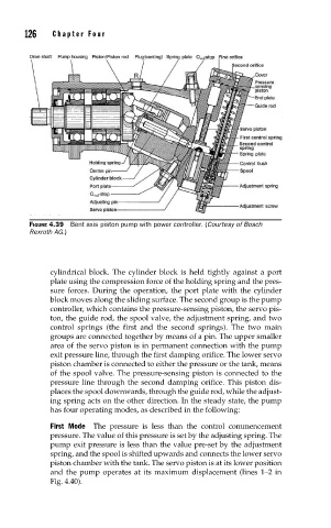
FIGURE 4.39 Bent axis piston pump with power controller. (Courtesy of Bosch
Rexroth AG.)
cylindrical block. The cylinder block is held tightly against a port
plate using the compression force of the holding spring and the pres-
sure forces. During the operation, the port plate with the cylinder
block moves along the sliding surface. The second group is the pump
controller, which contains the pressure-sensing piston, the servo pis-
ton, the guide rod, the spool valve, the adjustment spring, and two
control springs (the first and the second springs). The two main
groups are connected together by means of a pin. The upper smaller
area of the servo piston is in permanent connection with the pump
exit pressure line, through the first damping orifice. The lower servo
piston chamber is connected to either the pressure or the tank, means
of the spool valve. The pressure-sensing piston is connected to the
pressure line through the second damping orifice. This piston dis-
places the spool downwards, through the guide rod, while the adjust-
ing spring acts on the other direction. In the steady state, the pump
has four operating modes, as described in the following:
First Mode The pressure is less than the control commencement
pressure. The value of this pressure is set by the adjusting spring. The
pump exit pressure is less than the value pre-set by the adjustment
spring, and the spool is shifted upwards and connects the lower servo
piston chamber with the tank. The servo piston is at its lower position
and the pump operates at its maximum displacement (lines 1–2 in
Fig. 4.40).