
Page 153 - Fluid Power Engineering
P. 153
Hydraulic Pumps 127
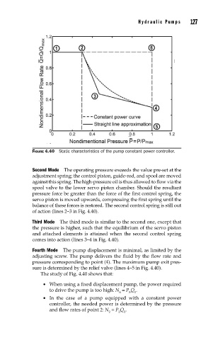
FIGURE 4.40 Static characteristics of the pump constant power controller.
Second Mode The operating pressure exceeds the value pre-set at the
adjustment spring; the control piston, guide-rod, and spool are moved
against this spring. The high-pressure oil is thus allowed to flow via the
spool valve to the lower servo piston chamber. Should the resultant
pressure force be greater than the force of the first control spring, the
servo piston is moved upwards, compressing the first spring until the
balance of these forces is restored. The second control spring is still out
of action (lines 2–3 in Fig. 4.40).
Third Mode The third mode is similar to the second one, except that
the pressure is higher, such that the equilibrium of the servo piston
and attached elements is attained when the second control spring
comes into action (lines 3–4 in Fig. 4.40).
Fourth Mode The pump displacement is minimal, as limited by the
adjusting screw. The pump delivers the fluid by the flow rate and
pressure corresponding to point (4). The maximum pump exit pres-
sure is determined by the relief valve (lines 4–5 in Fig. 4.40).
The study of Fig. 4.40 shows that:
• When using a fixed displacement pump, the power required
to drive the pump is too high: N = P Q .
6 5 1
• In the case of a pump equipped with a constant power
controller, the needed power is determined by the pressure
and flow rates of point 2: N = P Q .
2 2 2