
Page 146 - Fluid Power Engineering
P. 146
120 Cha pte r F o u r
against the pressures inside the pumping chambers. Because of this,
an optimum clearance between the rotor and the side plates is guaran-
teed, and the side clearance leakage is minimized.
Tip Clearance Leakage
The tip clearance leakage takes place through the clearance between
the blade tip and the inner surface of the cam ring. Therefore, the
blade root should be pressurized wherever the blade separates two
chambers of different pressure (see Fig. 4.34c and 4.34d). Otherwise,
wherever the blade separates two chambers of equal pressure, the
blade root should have the same pressure as that in these chambers
(see Fig. 4.34a and 4.34b). In this way, the blade is pressure balanced
and is pushed radially outwards under the action of the centrifugal
force only. This zone of blade displacement has minimal friction and
reduced wear.
Most of the pressure-balanced vane pumps have an intra-vane
feature. This design helps keep the vane in continuous contact with
the cam ring during the rises and falls while minimizing the vane-tip
contact force. The construction of the intra-vane structure is illustrated
in Fig. 4.32. Instead of a single vane, there are two vanes of the same
thickness. A smaller one (intra vane 6) is installed at the inner side of
the main vane (4), which creates an inner chamber (intra-vane cham-
ber) between them (5).
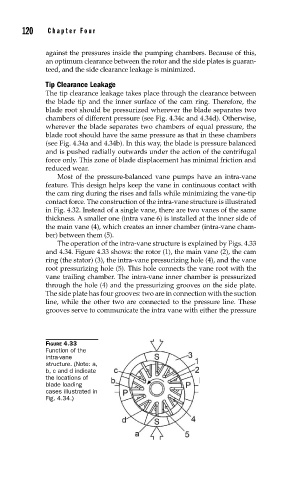
The operation of the intra-vane structure is explained by Figs. 4.33
and 4.34. Figure 4.33 shows: the rotor (1), the main vane (2), the cam
ring (the stator) (3), the intra-vane pressurizing hole (4), and the vane
root pressurizing hole (5). This hole connects the vane root with the
vane trailing chamber. The intra-vane inner chamber is pressurized
through the hole (4) and the pressurizing grooves on the side plate.
The side plate has four grooves: two are in connection with the suction
line, while the other two are connected to the pressure line. These
grooves serve to communicate the intra vane with either the pressure
FIGURE 4.33
Function of the
intra-vane
structure. (Note: a,
b, c and d indicate
the locations of
blade loading
cases illustrated in
Fig. 4.34.)