
Page 140 - Fluid Power Engineering
P. 140
114 Cha pte r F o u r
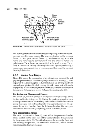
FIGURE 4.25 Pressure and gear contact forces acting on the gears.
The bearing lubrication is another factor imposing minimum recom-
mended speed in some pumps. The gears are loaded by the pressure
forces, F , and gear contact forces, F , as shown in Fig. 4.25. The
P C
rotors are nonpressure compensated and the pressure forces are
unbalanced. These forces are transmitted to the shaft bearing. There-
fore, in the case of sliding a bearing lubricated hydrodynamically, a
minimum pump speed, n , is recommended to insure the required
min
bearing lubrication.
4.6.9 Internal Gear Pumps
Figure 4.26 shows the construction of an internal gear pump of the leak
gap compensated type. The shown pump consists of: a housing (1), bear-
ing cover (1.1), blanking plate (1.2), internal gear (2), driving shaft with
external gear (pinion) (3), shaft bearing (4), side, wear plates (5), and a
stop pin (6), as well as the segment assembly (7), which is comprised of
the segment (7.1), segment carrier (7.2), and the sealing rolls (7.3).
The Suction and Displacement Process
The pinion (3), which is carried in the hydrodynamic bearings, drives
the internal toothed ring gear (2). During the rotation, a negative pres-
sure is produced in the un-meshing zone and the fluid flows into the
pump through a hole in the side plate. The segment assembly (7) sep-
arates the suction chamber from the delivery chamber. The two gears
mesh in the delivery zone, displacing the oil out of the pump.
Axial Compensation Forces
The axial compensation force, F , acts within the pressure chamber
A
areas, located on the outer side of the wear plates (5). It is generated
by the pressure field (8). The side clearances, between the fixed and
the rotating components, are extremely minimized, which insures
minimum side clearance leakage.