
Page 136 - Fluid Power Engineering
P. 136
110 Cha pte r F o u r
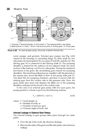
1. Housing, 2. Mounting flange, 3. Drive shaft, 4. Two bearing blocks, side plates,
5. Bearing bush, 6. Discs, 7 and 8. Inlet and exit ports, 9. Driving gear, 10. Driven gear
FIGURE 4.22 An external gear pump. (Courtesy of Bosch Rexroth AG.)
screw pumps, and gerotors. External gear pumps (see Fig. 4.22)
consist of: the housing (1), mounting flange (2), drive shaft (3), two
side plates (4), bearing bush (5), two gears (9 and 10), and disc (6). The
driving gear (9) is connected to the driving shaft (3). The pumping
chamber is formed by the surfaces of two adjacent teeth, the inner
surface of the housing, and the two side plates. During the rotational
movement of the gears, the un-meshing gears release the pumping
chambers. The resulting underpressure, together with the pressure in
the suction line, forces the fluid to flow to the pump inlet port (7).
This fluid fills the pumping chambers, and then is moved with the
rotating gear from the suction side to the pressure side. Here, the
gears mesh once more and displace the fluid out of the pumping
chambers and prevent its return to the suction zone.
In the case of an external gear pump with two spur gears, the
pump geometric volume is given by the following relation:
2
V = 2π bm z +( sin 2 γ) (4.30)
g
where b = Tooth length, m
m = Module of tooth, m
z = Number of teeth per gear
γ = Pressure angle of tooth, rad
Internal Leakage in External Gear Pumps
The internal leakage in gear pumps takes place through two main
paths:
• Over the tip of the tooth, tip clearance leakage
• Between the sides of the gears and the side plates, side clearance
leakage.