
Page 58 - Fluid Power Engineering
P. 58
Hydraulic Oils and Theor etical Backgr ound 35
This form of continuity equation is widely applied in the fluid
power system’s analysis. The difference (Q − Q = Q ) is due to oil
1
2
C
compressibility, where
Q = V dP = C dP (2.66)
C B dt dt
π DL
2
where C = (2.67)
4 B
The term C is called the hydraulic capacitance of the line. This
capacitance is analogous to the electric capacitance since it has an
energy storing effect and is described mathematically by the same
expression: i = C de dt.
/
Sometimes, the pipe wall deformation is not negligible. In such
cases, it should be taken into consideration when calculating the hy-
draulic capacitance. The variation of volume of pipe line, ΔV , de-
L
pends on the pipe length, the line material, wall thickness, diameter,
and system pressure. The walls deform due to the combined effect of
the radial and axial pressure forces. An expression for this volumetric
variation due to a pressure increment ΔP is derived as follows.
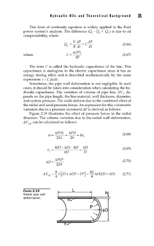
Figure 2.19 illustrates the effect of pressure forces in the radial
direction. The volume variation due to the radial wall deformation,
ΔV , can be calculated as follows:
LR
ΔPDL ΔPD
σ = = = E ε (2.68)
2 hL 2 h r
)
ε = π D +( Δ D − πD = Δ D (2.69)
r πD D
ΔD = ΔPD 2 (2.70)
2 Eh
π π L
{
2
2
(
ΔV = L D + ΔD − } = ΔDD + ΔD) (2.71)
2
(
)
D
LR 4 4
FIGURE 2.19
Radial pipe wall
deformation.