
Page 59 - Fluid Power Engineering
P. 59
36 Cha pte r T w o
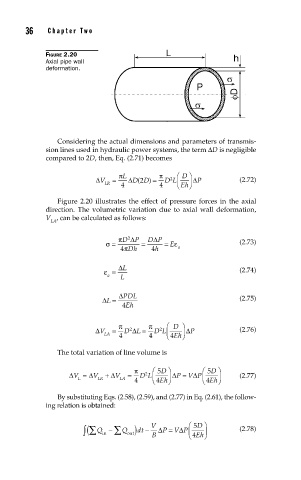
FIGURE 2.20
Axial pipe wall
deformation.
Considering the actual dimensions and parameters of transmis-
sion lines used in hydraulic power systems, the term ΔD is negligible
compared to 2D, then, Eq. (2.71) becomes
π L π ⎛ D ⎞
2
)
(
2
ΔV = ΔDD = D L ⎜ ⎟ ΔP (2.72)
LR 4 4 ⎝ Eh⎠
Figure 2.20 illustrates the effect of pressure forces in the axial
direction. The volumetric variation due to axial wall deformation,
V , can be calculated as follows:
LA
πD Δ P DP
Δ
2
σ = = = E ε (2.73)
4 πDh 4 h a
Δ L
ε = (2.74)
a L
ΔL = ΔPDL (2.75)
4 Eh
π π ⎛ D ⎞
2
ΔV = D 2 ΔL = D L ⎜ ⎟ ΔP (2.76)
LA 4 4 ⎝ 4 Eh⎠
The total variation of line volume is
π ⎛ 5 D ⎞ ⎛ 5 D ⎞
ΔV = ΔV + ΔV = D L ⎜ ⎟ ΔP = V ΔP ⎜ ⎜ ⎟ (2.77)
2
L LR LA Eh⎠ Eh⎠
4 ⎝ 4 ⎝ 4
By substituting Eqs. (2.58), (2.59), and (2.77) in Eq. (2.61), the follow-
ing relation is obtained:
D ⎞
in ∑
∫ (∑ Q − Q ) dt − V Δ P = Δ ⎛ 5 Eh⎠ ⎟ (2.78)
⎜
V P
out
⎝ 4
B