
Page 355 - Fluid-Structure Interactions Slender Structure and Axial Flow (Volume 1)
P. 355
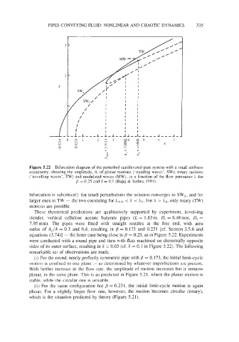
PIPES CONVEYING FLUID: NONLINEAR  AND CHAOTIC DYNAMICS         335
                                                                     -7


                                                            TW       0


                                               ’
                                           /L/+       I    I
                                                           I
                                              k’      I    I
                                            /         I    I
                                           /  I       I    I  I
                                                      I
                            fy                I  I :   I  I  I   1  I  I
                                              I
                                  I
                                              I
                                                      I  I  I   I  I I
                          /I  .i                      I  I   I  I


             Figure 5.22  Bifurcation diagram of  the perturbed cantilevered pipe system with a small stiffness
              asymmetry, showing the amplitude, A, of  planar motions (‘standing waves’, SW), rotary motions
              (‘travelling waves’,  TW) and modulated waves  (MW), as a function of  the flow  parameter h for
                                 #I 0.25 and S = 0.1 (Bajaj & Sethna 1991).
                                   =

             bifurcation is subcritical): for small perturbations the solution converges to SW,,  and for
              larger ones to TW - the two coexisting for Amin  < h < A/,. For h > A/,, only rotary (TW)
              motions are possible.
                These  theoretical  predictions  are  qualitatively  supported  by  experiment,  involving
              slender,  vertical  cellulose  acetate  butyrate  pipes  (L = 1.83 m,  D, = 6.48 mm,  D,,  =
              7.95mm).  The  pipes  were  fitted  with  straight  nozzles  at  the  free  end,  with  area
              ratios  of  A,/A  = 0.3 and  0.4, resulting  in  /3  = 0.173  and  0.231  [cf.  Section 3.5.6  and
              equations (3.74)] - the latter case being close to /3  = 0.25, as in Figure 5.22. Experiments
              were conducted with  a round pipe  and then with flats machined on diametrally opposite
              sides of its outer surface, resulting in 6 2 0.05 (cf. 6 = 0.1 in Figure 5.22). The following
              remarkable set of  observations are made.
                (i) For the round, nearly perfectly symmetric pipe with /3  = 0.173, the initial limit-cycle
              motion  is confined to one plane - as determined by  whatever imperfections are present.
             With  further increase in  the flow rate, the amplitude of motion  increases but it remains
             planar, in the same plane.  This is as predicted in Figure 5.21, where the planar motion is
             stable, while the circular one is unstable.
                (ii) For  the  same configuration but  /3  = 0.231,  the  initial  limit-cycle motion  is  again
             planar.  For  a  slightly  larger  flow  rate,  however,  the  motion  becomes  circular  (rotary),
             which is the situation predicted by  theory (Figure 5.21).