
Page 438 - Fluid-Structure Interactions Slender Structure and Axial Flow (Volume 1)
P. 438
410 SLENDER STRUCTURES AND AXIAL FLOW
Forcing frequency, w
0.35 E"'"'"''''"'3
- 0.30
01
2 0.25
C
$ 0.20
8
3 0.15
'S
ti 0.10
8
0.05
0.00
(b) Forcing frequency, w
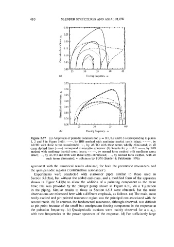
Figure 5.67 (a) Amplitude of periodic solutions for ,u = 0.1,0.2 and 0.3 (corresponding to points
1, 2 and 3 in Figure 5.66): -, by IHB method with nonlinear inertial terms intact; --.--, by
AUTO with these terms transformed; . . ., by AUTO with these terms wholly eliminated; in all
cases dashed lines (---) correspond to unstable solutions: (b) Results for ,u = 0.3: -, by IHB
method with nonlinear inertial terms intact; by normal form method with nonlinear terms
intact; . . ., by AUTO and IHB with these terms eliminated; -.-, by normal form method, with all
such terms eliminated; 0, solutions by FDM (Semler & Pdidoussis 1996).
agreement with the numerical results obtained, for both the parametric resonances and
the quasiperiodic regions ('combination resonances').
Experiments were conducted with elastomer pipes similar to those used in
Section 5.8.3(a), but without the added end-mass, and a modified form of the apparatus
shown in Figure 5.43(b) to allow the addition of a pulsating component to the mean
flow; this was provided by the plunger pump shown in Figure 4.30, via a T-junction
in the piping. Similar results to those in Section 4.5.3 were obtained, but the main
observations are reiterated here with a different emphasis, as follows. (a) The main, most
easily excited and pin-pointed resonance region was the principal one associated with the
second mode. (b) In contrast, the fundamental resonance, although observed, was difficult
to pin-point because of the small but omnipresent forcing component in the response at
the pulsation frequency. (c) Quasiperiodic motions were mainly observed for u > u,f,
with two frequencies in the power spectrum of the response. (d) For sufficiently large