
Page 471 - Fluid-Structure Interactions Slender Structure and Axial Flow (Volume 1)
P. 471
442 SLENDER STRUCTURES AND AXIAL FLOW
It is of interest to recall that for the inextensible case, 10 or so elements lead to
convergence of the results (Section 6.4.1), as opposed to more than 30 elements required
for the extensible case. Thus, the extensible analysis is computationally more demanding.
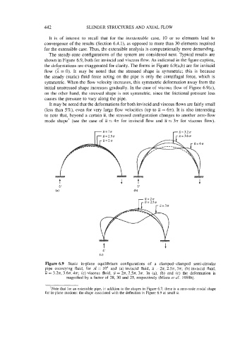
The steady-state configurations of the system are considered next. Typical results are
shown in Figure 6.9, both for inviscid and viscous flow. As indicated in the figure caption,
the deformations are exaggerated for clarity. The forms in Figure 6.9(a,b) are for inviscid
flow (Z = 0). It may be noted that the stressed shape is symmetric; this is because
the steady (static) fluid force acting on the pipe is only the centrifugal force, which is
symmetric. When the flow velocity increases, this symmetric deformation away from the
initial unstressed shape increases gradually. In the case of viscous flow of Figure 6.9(c),
on the other hand, the stressed shape is not symmetric, since the frictional pressure loss
causes the pressure to vary along the pipe.
It may be noted that the deformations for both inviscid and viscous flows are fairly small
(less than 5%), even for very large flow velocities (up to U = 6n). It is also interesting
to note that, beyond a certain U, the stressed configuration changes to another zero-flow
mode shapet (see the case of U = 4n for inviscid flow and U = 3n for viscous flow).
c
Figure 6.9 Static in-plane equilibrium configurations of a clamped-clamped semi-circular
pipe conveying fluid, for Se = lo4 and (a) inviscid fluid, ti = 2n, 2Sx, 371; (b) inviscid fluid,
-
u = 3.2n, 3.671, 4n; (c) viscous fluid, U = 27r, 2Sn, 3n. In (a), (b) and (c) the deformation is
magnified by a factor of 28, 30 and 25, respectively (Misra et al. 1988b).
+Note that for an extensible pipe, in addition to the shapes in Figure 6.7, there is a zero-node modal shape
for in-plane motions: the shape associated with the deflection in Figure 6.9 at small U.