
Page 69 - Fluid-Structure Interactions Slender Structure and Axial Flow (Volume 1)
P. 69
52 SLENDER STRUCTURES AND AXIAL FLOW
Argand plane, as U is vaned. Figure 2.10 shows the development of (a) divergence and
(b) flutter in these two representations. The solution to (2.161) may be expressed as
x = Ae-mll' sin(Q,, dpr + 4), (2.162)
or, in terms of the eigenvalues A and eigenfrequencies Q, by
x = Ae'"(A)r sin[9ni(A) + 41 = Ae-4m(02)' sin[%e(Q) + 41, (2.163)
9nt (A) 4111 (0)
0
9rn (A)
Valu
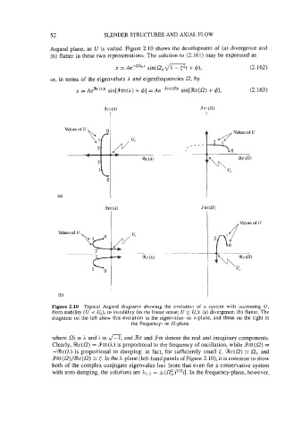
Figure 2.10 Typical Argand diagrams showing the evolution of a system with increasing U,
from stability (U i Uc), to instability (in the linear sense; U 2 Uc): (a) divergence; (b) flutter. The
diagrams on the left show this evolution in the eigenvalue- or A-plane, and those on the right in
the frequency- or SZ-plane.
%e
where Qi = h and i = a, and 9im denote the real and imaginary components.
and
Clearly, %e(Q) = 9ni(A) is proportional to the frequency of oscillation, while 4m(Q) =
-%e@) is proportional to damping; in fact, for sufficiently small {, %e(R) zz R, and
9tn(R)/%e(Q) = <. In the A-plane (left-hand panels of Figure 2.10), it is common to show
both of the complex conjugate eigenvalue loci [note that even for a conservative system
with zero damping, the solutions are Al,2 = ~t(Ri)'/~i]. In the frequency-plane, however,