
Page 104 - Fluid mechanics, heat transfer, and mass transfer
P. 104
FLOW MEASUREMENT 81
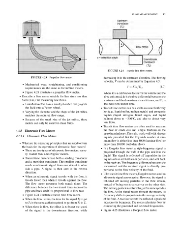
FIGURE 4.24 Transit time flow meter.
Propeller flow meter. decreasing it in the upstream direction. The flowing
FIGURE 4.23
velocity, V can be determined by Equation 4.5.
& Mechanical wear, straightening, and conditioning
V ¼ Kdt=T L ; ð4:7Þ
requirements are the same as for turbine meters.
& Figure 4.23 illustrates a propeller flow meter.
where K is a calibration factor for the volume and the
. Describe a flow meter suitable for line sizes less than time units used, dt is the time differential between the
5 cm (2 in.) for measuring low flows. upstream and the downstream transit times, and T L is
& Low-flow meters have a small jet orifice that projects the zero flow transit time.
the fluid onto a Pelton wheel. & Transit time meters can be used to measure both very
& Varying the diameter and the shape of the jet orifice hot (e.g., liquid sulfur, molten metals) and cryogenic
matches the required flow range. liquids (liquid nitrogen, liquid argon, and liquid
& Because of the small size of the jet orifice, these helium) down to 300 C, and also to detect very
meters can only be used for clean fluids. low flows.
& Transit time flow meters are often used to measure
the flow of crude oils and simple fractions in the
4.1.5 Electronic Flow Meters
petroleum industry. They alsowork well with viscous
4.1.5.1 Ultrasonic Flow Meters liquids, provided that the Reynolds number at min-
imum flow is either less than 4000 (laminar flow) or
. What are the operating principles that are used to form
more than 10,000 (turbulent flow).
the basis for the operation of ultrasonic flow meters?
& In a Doppler flow meter, a high-frequency signal is
& There are two types of ultrasonic flow meters, name-
projected through the wall of the pipe and into the
ly, transit time and Doppler meters.
liquid. The signal is reflected off impurities in the
& Transit time meters have both a sending transducer
liquid such as air bubbles or particles, and sent back
and a receiving transducer. The sending transducer to the receiver. The frequency difference between the
sends an ultrasonic signal from one side of to other transmitted and the received signal is directly pro-
side a pipe. A signal is then sent in the reverse portional to the flow velocity of the fluid.
direction.
& Like transit time flow meters, Doppler meters send an
& When an ultrasonic signal travels with the flow, it
ultrasonic signal across a pipe. However, the signal is
travels faster than when it travels against the flow.
reflected off moving particles in the flow stream,
The flow meter measures both transit times. The
instead of being sent to a receiver on the other side.
difference between the two transit times (across the
Themovingparticlesaretravelingatthesamespeedas
pipe and back again) is proportional to flow rate. the flow. As the signal passes through the stream, its
& Figure 4.24 illustrates transit time flow meter. frequency shifts in proportion to the average velocity
& When the flow is zero, the time for the signal T 1 to get of the fluid. A receiver detects the reflected signal and
to T 2 is the same as that required to get from T 2 to T 1 . measures its frequency. The meter calculates flow by
& When there is flow, the effect is to boost the speed comparing the generated and detected frequencies.
of the signal in the downstream direction, while & Figure 4.25 illustrates a Doppler flow meter.