
Page 109 - Fluid mechanics, heat transfer, and mass transfer
P. 109
FLOW MEASUREMENT
86
& If a tube is rotated around a point while liquid is
flowing through it (toward or away from the center of
rotation), that fluid will generate an inertial force
(acting on the pipe) that will be at right angles to the
direction of the flow.
& Naturally, rotating a tube is not practical when build-
ing a commercial flow meter, but oscillating or
vibrating the tube can achieve the same effect.
& Coriolis flow meters are made up of one or more
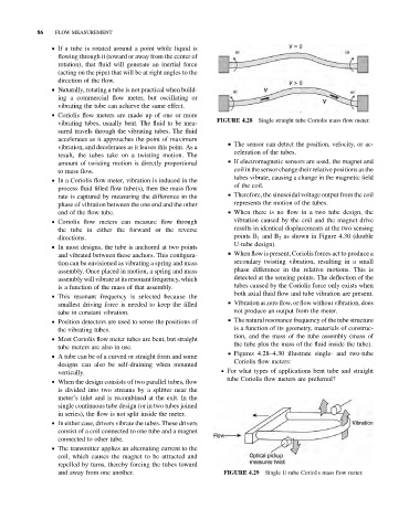
vibrating tubes, usually bent. The fluid to be mea- FIGURE 4.28 Single straight tube Coriolis mass flow meter.
sured travels through the vibrating tubes. The fluid
accelerates as it approaches the point of maximum
& The sensor can detect the position, velocity, or ac-
vibration, and decelerates as it leaves this point. As a
celeration of the tubes.
result, the tubes take on a twisting motion. The
amount of twisting motion is directly proportional & If electromagnetic sensors are used, the magnet and
to mass flow. coil in the sensor change their relative positions as the
tubes vibrate, causing a change in the magnetic field
& In a Coriolis flow meter, vibration is induced in the
of the coil.
process fluid filled flow tube(s), then the mass flow
& Therefore, the sinusoidal voltage output from the coil
rate is captured by measuring the difference in the
phase of vibration between the one end and the other represents the motion of the tubes.
end of the flow tube. & When there is no flow in a two tube design, the
& Coriolis flow meters can measure flow through vibration caused by the coil and the magnet drive
the tube in either the forward or the reverse results in identical displacements at the two sensing
directions. points B 1 and B 2 as shown in Figure 4.30 (double
U-tube design).
& In most designs, the tube is anchored at two points
& When flow is present, Coriolis forces act to produce a
and vibrated between these anchors. This configura-
tion can be envisioned as vibrating a spring and mass secondary twisting vibration, resulting in a small
assembly. Once placed in motion, a spring and mass phase difference in the relative motions. This is
assembly will vibrateat its resonant frequency, which detected at the sensing points. The deflection of the
is a function of the mass of that assembly. tubes caused by the Coriolis force only exists when
both axial fluid flow and tube vibration are present.
& This resonant frequency is selected because the
smallest driving force is needed to keep the filled & Vibration at zero flow, or flow without vibration, does
tube in constant vibration. not produce an output from the meter.
& Position detectors are used to sense the positions of & The natural resonance frequency of the tube structure
the vibrating tubes. is a function of its geometry, materials of construc-
tion, and the mass of the tube assembly (mass of
& Most Coriolis flow meter tubes are bent, but straight
the tube plus the mass of the fluid inside the tube).
tube meters are also in use.
& Figures 4.28–4.30 illustrate single- and two-tube
& A tube can be of a curved or straight form and some
Coriolis flow meters:
designs can also be self-draining when mounted
vertically. . For what types of applications bent tube and straight
tube Coriolis flow meters are preferred?
& When the design consists of two parallel tubes, flow
is divided into two streams by a splitter near the
meter’s inlet and is recombined at the exit. In the
single continuous tube design (or in two tubes joined
in series), the flow is not split inside the meter.
& In either case, drivers vibrate the tubes. These drivers
consist of a coil connected to one tube and a magnet
connected to other tube.
& The transmitter applies an alternating current to the
coil, which causes the magnet to be attracted and
repelled by turns, thereby forcing the tubes toward
and away from one another. FIGURE 4.29 Single U-tube Coriolis mass flow meter.