
Page 107 - Fluid mechanics, heat transfer, and mass transfer
P. 107
FLOW MEASUREMENT
84
is linear over the entire flow meter range. For this
reason, flow tubes are usually calibrated at only one
velocity.
& Magnetic meters can measure flow in both directions,
as reversing direction will change the polarity but not
the magnitude of the signal.
& The K value obtained by water testing might not be
valid for non-Newtonian fluids (with velocity-depen-
dent viscosity) or magnetic slurries (those containing
magnetic particles). These types of fluids can affect
the density of the magnetic field in the tube.
& In-line calibration and special compensating designs
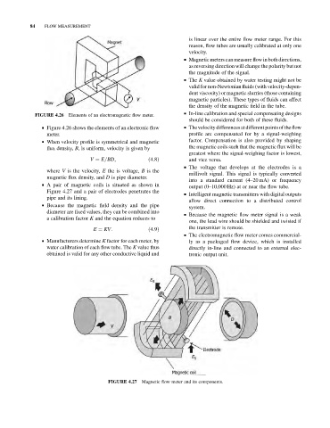
Elements of an electromagnetic flow meter.
FIGURE 4.26
should be considered for both of these fluids.
& Figure 4.26 shows the elements of an electronic flow & Thevelocity differences at different points of the flow
meter. profile are compensated for by a signal-weighing
& When velocity profile is symmetrical and magnetic factor. Compensation is also provided by shaping
flux density, B, is uniform, velocity is given by the magnetic coils such that the magnetic flux will be
greatest where the signal-weighing factor is lowest,
V ¼ E=BD; ð4:8Þ and vice versa.
& The voltage that develops at the electrodes is a
where V is the velocity, E the is voltage, B is the
millivolt signal. This signal is typically converted
magnetic flux density, and D is pipe diameter.
into a standard current (4–20 mA) or frequency
& A pair of magnetic coils is situated as shown in
output (0–10,000 Hz) at or near the flow tube.
Figure 4.27 and a pair of electrodes penetrates the
& Intelligent magnetic transmitters with digital outputs
pipe and its lining.
allow direct connection to a distributed control
& Because the magnetic field density and the pipe
system.
diameter are fixed values, they can be combined into
& Because the magnetic flow meter signal is a weak
a calibration factor K and the equation reduces to
one, the lead wire should be shielded and twisted if
E ¼ KV: ð4:9Þ the transmitter is remote.
& The electromagnetic flow meter comes commercial-
& Manufacturers determine K factor for each meter, by ly as a packaged flow device, which is installed
water calibration of each flow tube. The K value thus directly in-line and connected to an external elec-
obtained is valid for any other conductive liquid and tronic output unit.
Magnetic flow meter and its components.
FIGURE 4.27