
Page 69 - Fluid mechanics, heat transfer, and mass transfer
P. 69
PIPING, SEALS, AND VALVES
46
& Maximum velocities for saturated steam lines should
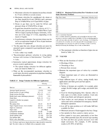
TABLE 3.4 Maximum Hydrocarbon Flow Velocities to Avoid
be 37 m/s (120 ft/s) to avoid erosion. Static Electricity Problems
& Maximum velocities for superheated, dry steam or Pipe Size (mm) Maximum Velocity (m/s)
gas lines should be 61 m/s (200 ft/s) and a pressure
10 8.0
drop of 10 kPa/100 m (or 0.5 psi/100 ft) of pipe.
25 4.9
& Steam or gas lines can be sized for 6D m/s and 50 3.5
pressure drops of 10 kPa/100 m of pipe. 100 2.5
200 1.8
& Liquid lines should be sized for a velocity of (1.5 þ
D/3) m/s and a pressure drop of 40 kPa/100 m (2 psi/ 400 1.3
100 ft) of pipe at pump discharges. Generally, veloc- 600 þ 1.0
ities are in the range of 1–3 m/s, depending on the Source: Australian Standard.
nature of liquids. Note: (1) Static electricity generation and accumulation increases with
decrease in electrical conductivity of the fluids. (2) The conducting pipeline
& In preliminary estimates, line pressure drops may be
wall, well grounded, provides the path of static discharge. (3) It should be
set for an equivalent length of 30 m of pipe between noticed that the velocities are to be reduced with increased pipe sizes as
each piece of equipment. increased pipe sizes increases the path of discharge of static electricity
. For the same line size, design velocities are more for thereby decreasing the discharge rate of static accumulation.
saturated vapors compared to gas/superheated vapors.
True/False? & The maximum velocities as function of pipe size are
& False (other way round). listed in Table 3.4.
. Recommended optimum velocities in sizing piping
increase with increase in fluid densities. True/False? 3.3 VALVES
& False.
. What are the functions of valves?
. Summarize typical approximate design velocities for
& Blocking of flow.
process system applications.
& Throttling of flow.
& The typical design velocities for different applica-
& Prevent flow reversal.
tions are listed in Table 3.3.
. Illustrate the important types of valves by a suitable
. What are the recommended maximum velocities to
diagram.
avoid static electricity generation in pipelines handling
flammable hydrocarbons? & Some important types of valves are illustrated in
Figure 3.5.
. Name different types of valves, stating briefly their
applications and their good and bad aspects.
TABLE 3.3 Design Velocities for Different Applications
Velocity Gate Valves:
& Variety of designs are available, for example, plain
Service m/s ft/s
wedge, flexible wedge, split wedge, and double disk
Average liquid (process) 1.2–2.0 4–6.5 types.
Pump suction (except boiling) 0.3–1.5 1–5 & Used for blocking/stopping flow. Operate either in
Pump suction (boiling) 0.25–0.9 0.5–3
fully open or in fully closed condition. Used only
Boiler feed water (discharge pressure) 1.2–2.4 4–8
with clean fluids and infrequent operation.
Drain lines 0.46–1.2 1.5–4
& These bodies are used primary for hand-operated
Liquid to reboiler (no pump); 0.6–2.1 2–7
downcomer valves and valves automated for emergency shutoff.
Two-phase flow 10–23 35–75 Infrequent operation.
Vapor–liquid mixture from reboiler 4.6–9.1 15–30 & Low DP in open position as it will make full bore
Vapor to condenser 4.6–24 15–80 available for flow.
Vapor lines 0.3 Mach
& Minimum amount of fluid trapped in the line. Cheap.
Compressor suction 23–60 75–200
Compressor discharge 30–75 100–250 & Not suitable for flow control or slurry service.
Steam turbine inlet 35–100 120–320 & Flow control is very poor, particularly at low flow
Gas turbine inlet 45–100 150–350 rates. When partially open, the crescent-type opening
Relief valve discharge 0.5 Mach for flow and flow area greatly increases even with
slight movement. For example, 5–10% opening
Note: For heavy and viscous liquids, the above values should be reduced by
half. The above values are for fluids with no suspended solids. results in 85–95% of full flow.