
Page 72 - Fluid mechanics, heat transfer, and mass transfer
P. 72
VALVES 49
the valve is to be opened and closed frequently, leaks & Well suited for throttling service where precise
are possible. flow control is required. Several turns (four to six)
& Tight sealing and least maintenance problems. Low are required to open and closed the valve, making
cost. fine-tuning possible to achieve the desired flow
rate.
& Widely used for a range of services and outsells the
rotary type by a factor of 2. & Flow control is not good at low flow rates.
& Materials of construction, such as ceramics, per- & These valves do not permit contamination of flow
fluoro-alkoxy copolymer (PFA) and stainless steel medium; thus, they are used extensively in food
coated with corrosion and abrasive resistant materi- processing, pharmaceutical, brewing, and other ap-
als increase its range of applications. plications that cannot tolerate any contamination.
& For control applications, it is used in sizes less than & Suitable for corrosive fluids.
10 cm (4 in.). & Range is small.
& Not as good as globe valve for modulating control. & Not suitable for high-pressure and high-temperature
& Poor throttling capability. applications.
& Not good option for corrosives or processes where & Small movement of diaphragm is enough for opening
cavitation may be a problem. or closing.
& Fluid can get trapped under closed condition increas- & DP across the valve is higher than that for full bore
ing inventory of fluids, which gives rise to hazardous valves.
conditions. & Diaphragms may be made from rubber with fabric
& Special ball valves are available for three way ap- reinforcement and coated/lined with Teflon. Thin
plications and with vented balls. corrosion-resistant metal wall diaphragms are also
used for some applications.
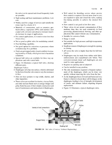
& Figure 3.8 illustrates a typical ball valve, showing
different parts. & Requires no packing and is leakproof.
Diaphragm Valves: & Can be installed in any position.
& Diaphragm valve has one surface, which is deformed & The only maintenance required is frequent replace-
by the force from thevalve stem to vary the resistance ment of the diaphragm, which can be done very
to flow. quickly without removing the valve from the line.
& Does not have pockets to trap solids, slurries, and & As the diaphragm flexes forward and backward on a
other impurities. frame to which it is fixed, there will be fatigue on the
& These valves are excellent for slurries, viscous fluids, diaphragm, leading to loss of strength, development
and other unclean fluids such as sewage sludges and of cracks, and ultimate failure, requiring frequent
gritty fluids because of their simple construction and replacement.
ease of maintenance and replacement of diaphragms. & Figure 3.9 illustrates a typical diaphragm valve.
Ball valve. (Courtesy: Vaishnavi Engineering.)
FIGURE 3.8