
Page 263 - Forensic Structural Engineering Handbook
P. 263
DESIGN ERRORS, CONSTRUCTION DEFECTS, AND PROJECT MISCOMMUNICATION 8.3
used to describe design elements that occur on every project such as steel beam to column
connections, reinforcing layout in beams, slabs and columns, and the innumerable details
shown to describe code required principles. Special or nonstandard connections such as
those in steel trusses must be fully detailed. The difficulty often arises in deciding what con-
stitutes nonstandard conditions. When such details are missing in a set of construction doc-
uments disputes arise that can lead to claims or even litigation. Designers should take a
conservative approach in such cases and over detail rather than under detail. Another prin-
ciple in detailing is not to repeat information shown on one detail to another. The reason
for this is that if changes are made for instance to a dimension, if it were shown on multi-
ple details, the change could be missed on one or more of them causing confusion and the
possibility of a contractor’s claim.
Clarity and Completeness of Designs. It should be obvious that design documents should
clearly define the intent of the design. However, this issue is often subject to misunder-
standing. What is clear to a designer may be confusing or incomplete in the opinion of a
detailer or contractor. It is therefore prudent to review design documents for clarity by inde-
pendently checking within a design office to make certain that no confusion exists in the
interpretation of the design drawings.
In the following sections, we review some examples that illustrate aspects of such
design issues.
Did a Bolt Collapse an Arena
On June 4, 1979, at about 6:45 p.m., a downpour of 4.25 in/h began falling on the Kansas
City area accompanied by a north wind gusting at 70 mph. About 25 minutes later, the cen-
tral third of the Kemper Memorial Arena hanging roof collapsed onto the unoccupied arena.
One acre of concrete and steel fell with such violence that it blew out some of the walls of
the arena. Kansas City and the engineering community were stunned, especially considering
that the arena had withstood for nearly 6 years storms and winds more severe than those of
June 4, 1979. Retained by a subcontractor on the construction team, Weidlinger Associates
investigated the collapse.
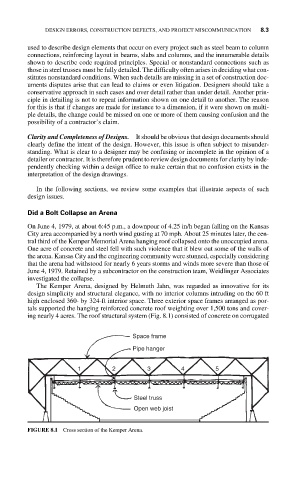
The Kemper Arena, designed by Helmuth Jahn, was regarded as innovative for its
design simplicity and structural elegance, with no interior columns intruding on the 60 ft
high enclosed 360- by 324-ft interior space. Three exterior space frames arranged as por-
tals supported the hanging reinforced concrete roof weighting over 1,500 tons and cover-
ing nearly 4 acres. The roof structural system (Fig. 8.1) consisted of concrete on corrugated
Space frame
Pipe hanger
1 2 3 4 5
Steel truss
Open web joist
FIGURE 8.1 Cross section of the Kemper Arena.