
Page 266 - Forensic Structural Engineering Handbook
P. 266
8.6 CAUSES OF FAILURES
sprouted and much of these hypothesized defective materials or defective workmanship. As
often happens, these theories turned out as sound as the effort it took to postulate them! But
it took a year for the National Bureau of Standards (NBS) to release the results of its inves-
1
tigation into the “most probable cause of failure.” As is customary, NBS did not assign
blame to any party but it made it clear that the responsibility for the collapse could be
mainly attributed to the structural engineers, who eventually lost their licenses in Missouri.
Other than at the ends, the walkways were supported by three intermediate transverse
box beams, fabricated by butt welding along their entire length of two 8-in-deep channels.
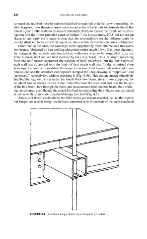
As designed, the second- and fourth-floor walkways were to be suspended from the
same 1-1/4-in steel rod and held in place by nuts (Fig. 8.4a). Thus the single rods hung
from the roof trusses supported the weights of both walkways, but the box beams of
each walkway supported only the loads of that single walkway. In the submitted shop
drawings, the contractor modified the design to use two offset hanger rods instead of a con-
tinuous one and the architect and engineer stamped the shop drawing as “approved” and
“reviewed,” respectively, without checking it (Fig. 8.4b). This design change effectively
doubled the load on the nut under the fourth-floor box-beam, since it now supported the
weight of two walkways instead of one. Under this load, the upper rod nuts bent the flanges
of the box beam, tore through the holes and disconnected from the box beam, thus initiat-
ing the collapse, even though the actual live load just preceding the collapse was estimated
at one-seventh of the code- mandated design live load (Fig. 8.5).
Analysis of these two details by the NBS investigative team revealed that: (a) the original
rod hanger connection design would have supported only 60 percent of the code-mandated
FIGURE 8.4 Box-beam hanger detail: (a) as-designed, (b) as-built.