
Page 264 - Forensic Structural Engineering Handbook
P. 264
8.4 CAUSES OF FAILURES
Space frame
Pipe hanger
Hinge
Stiffeners Bolts
Base plate
Micarta plate
Plates
Stiffeners Top chord of
steel truss
Truss vertical
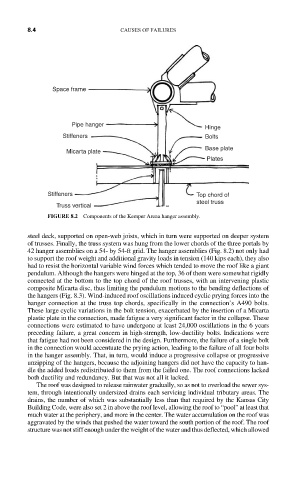
FIGURE 8.2 Components of the Kemper Arena hanger assembly.
steel deck, supported on open-web joists, which in turn were supported on deeper system
of trusses. Finally, the truss system was hung from the lower chords of the three portals by
42 hanger assemblies on a 54- by 54-ft grid. The hanger assemblies (Fig. 8.2) not only had
to support the roof weight and additional gravity loads in tension (140 kips each), they also
had to resist the horizontal variable wind forces which tended to move the roof like a giant
pendulum. Although the hangers were hinged at the top, 36 of them were somewhat rigidly
connected at the bottom to the top chord of the roof trusses, with an intervening plastic
composite Micarta disc, thus limiting the pendulum motions to the bending deflections of
the hangers (Fig. 8.3). Wind-induced roof oscillations induced cyclic prying forces into the
hanger connection at the truss top chords, specifically in the connection’s A490 bolts.
These large cyclic variations in the bolt tension, exacerbated by the insertion of a Micarta
plastic plate in the connection, made fatigue a very significant factor in the collapse. These
connections were estimated to have undergone at least 24,000 oscillations in the 6 years
preceding failure, a great concern in high-strength, low-ductility bolts. Indications were
that fatigue had not been considered in the design. Furthermore, the failure of a single bolt
in the connection would accentuate the prying action, leading to the failure of all four bolts
in the hanger assembly. That, in turn, would induce a progressive collapse or progressive
unzipping of the hangers, because the adjoining hangers did not have the capacity to han-
dle the added loads redistributed to them from the failed one. The roof connections lacked
both ductility and redundancy. But that was not all it lacked.
The roof was designed to release rainwater gradually, so as not to overload the sewer sys-
tem, through intentionally undersized drains each servicing individual tributary areas. The
drains, the number of which was substantially less than that required by the Kansas City
Building Code, were also set 2 in above the roof level, allowing the roof to “pool” at least that
much water at the periphery, and more in the center. The water accumulation on the roof was
aggravated by the winds that pushed the water toward the south portion of the roof. The roof
structure was not stiff enough under the weight of the water and thus deflected, which allowed