
Page 269 - Forensic Structural Engineering Handbook
P. 269
DESIGN ERRORS, CONSTRUCTION DEFECTS, AND PROJECT MISCOMMUNICATION 8.9
over the 200 vulnerable connections during a 3-month period. A potential disaster was
averted and LeMessurier, whose professional reputation could have been destroyed, was
lauded by many for his “courage” and “forthrightness”
Did we learn everything we should have known about wind by the late seventies?
Unfortunately not, as the following example illustrates. Consideration for wind-induced
torsion on a building was not incorporated into the ASCE 7 standard until the 1995 edition.
Furthermore, recent wind tunnel tests have shown that the initial torsional load require-
ments of ASCE 7-95 and 7-98 often grossly underestimate the true torsion on a building
under wind, including those that are symmetric in geometry and stiffness. This led to even
more stringent requirements in subsequent ASCE 7 editions. This is one of the issues we
encountered recently when we were asked to investigate a building exhibiting uncomfort-
able sway during high winds.
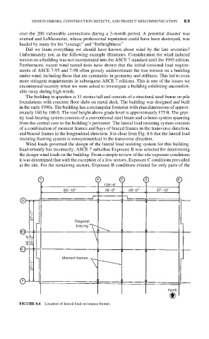
The building in question is 11 stories tall and consists of a structural steel frame on pile
foundations with concrete floor slabs on metal deck. The building was designed and built
in the early 1990s. The building has a rectangular footprint with plan dimensions of approx-
imately 160 by 100 ft. The roof height above grade level is approximately 175 ft. The grav-
ity load-bearing system consists of a conventional steel beam and column system spanning
from the central core to the building’s perimeter. The lateral load resisting system consists
of a combination of moment frames and bays of braced frames in the transverse direction,
and braced frames in the longitudinal direction. It is clear from Fig. 8.6 that the lateral load
resisting framing system is nonsymmetrical in the transverse direction.
Wind loads governed the design of the lateral load resisting system for this building.
Inadvertently but incorrectly, ASCE 7 suburban Exposure B was selected for determining
the design wind loads on the building. From a simple review of the site exposure conditions
it was determined that with the exception of a few sectors, Exposure C conditions prevailed
at the site. For the remaining sectors, Exposure B conditions existed for only parts of the
1 4 5 6 8
159'–8''
65'–10'' 28'–0'' 28'–0'' 37'–10''
A
37'–1''
Diagonal
bracing
B.9
94'–4'' 20'–2''
D.1
Moment frames
37'–1''
F
North
FIGURE 8.6 Location of lateral load resistance frames.