
Page 272 - Forensic Structural Engineering Handbook
P. 272
8.12 CAUSES OF FAILURES
investigation resulted in 30 recommendations, the second of which was: “NIST recom-
mends that nationally accepted performance standards be developed for (1) conducting
wind tunnel testing of prototype structures based on sound technical methods that result in
repeatable and reproducible results among testing laboratories; and (2) estimating wind
loads and their effects on tall buildings for use in design, based on wind tunnel testing data
and directional wind speed data.” 5
To the question of one or two occurrences, a federal jury in Manhattan, in December
2004, agreed with us that the collapses of the WTC Towers constituted two occurrences.
As to the question of whether we have conquered the wind, that jury is still out.
Stiffness Compatibility: Concrete Frame and CMU Shearwall Building
in an Earthquake
Located in Los Angeles, California, a six-story residential structure over two levels of park-
ing was constructed in 1972. The upper parking level is at grade and the lower one is subter-
ranean. Above the parking levels the building is constructed of reinforced masonry bearing
and shear walls composed of single-wythe 8 in nominal concrete masonry units, and the floor-
ing consists of 8-in-thick 4-ft-wide precast, prestressed hollow-core concrete planks that span
30 ft between CMU block walls. The planks are connected to the CMU block walls with bent
reinforcing bars. The lowest two levels of the precast concrete plank floors are topped with a
2.5-in-thick reinforced concrete for added fire separation from the parking levels. Reinforced
concrete transfer beams and columns are provided at the parking garage levels to accommo-
date the wide driving bays and to provide transition from the residential floors to parking levels.
These beams also support the weight of the CMU block walls in the residential floors directly
above the beams. The larger of these beams are 36 by 32 in, are located in the upper parking
(second floor) level spanning 31 ft over the interior driving bays, and are supported by 16–in-
diameter circular columns. The smaller beams over the exterior 31-ft bays are 22 by 30 in and
are supported by 16–in-wide square columns. The exterior walls, interior partition walls
between units, and the south walls of the hallway are constructed of CMU blocks.
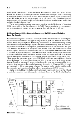
A plan of the building with the layout of walls on a typical floor is shown in Fig. 8.8 and
a vertical cross section (A-A’) through the building is shown in Fig. 8.9. The building has
A′
Driveway
to lower
level
garage
Down
Driveway to
upper level
garage
CMU block wall
A Steel stud drywall
FIGURE 8.8 Building plan.