
Page 274 - Forensic Structural Engineering Handbook
P. 274
8.14 CAUSES OF FAILURES
1/8'' 1/32'' 3/64'' 1/32''
South end North end
32''
Beam
36'' gridline 3 W (west) E (east)
WB
32'' E
B (bottom)
3/16 inches
1/64'' 1/64'' 3/16'' 3/64'' 1/32'' wide crack
32''
Beam
36''
gridline 4
WB
32'' E
Approximate location
of CMU wall termination
above beam
FIGURE 8.10 Cracks in second-floor transfer beams.
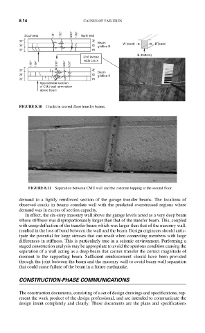
FIGURE 8.11 Separation between CMU wall and the concrete topping at the second floor.
demand to a lightly reinforced section of the garage transfer beams. The locations of
observed cracks in beams correlate well with the predicted overstressed regions where
demand was in excess of section capacity.
In effect, the six-story masonry wall above the garage levels acted as a very deep beam
whose stiffness was disproportionately larger than that of the transfer beam. This, coupled
with creep deflection of the transfer beam which was larger than that of the masonry wall,
resulted in the loss of bond between the wall and the beam. Design engineers should antic-
ipate the potential for large stresses that can result when connecting members with large
differences in stiffness. This is particularly true in a seismic environment. Performing a
staged construction analysis may be appropriate to avoid the spurious condition causing the
separation of a wall acting as a deep beam that cannot transfer the correct magnitude of
moment to the supporting beam. Sufficient reinforcement should have been provided
through the joint between the beam and the masonry wall to avoid beam-wall separation
that could cause failure of the beam in a future earthquake.
CONSTRUCTION-PHASE COMMUNICATIONS
The construction documents, consisting of a set of design drawings and specifications, rep-
resent the work product of the design professional, and are intended to communicate the
design intent completely and clearly. These documents are the plans and specifications