
Page 115 - Subyek Teknik Mesin - Forsthoffers Best Practice Handbook for Rotating Machinery by William E Forsthoffer
P. 115
Be st Practice 2 .23 Pump Best Practices
B.P. 2.22. Supporting Material Review pump maintenance site and company records to
discover what changeover periods have resulted in the highest
As stated in this best practice material above, we have found pump MTBFs.
that most plants do not practice a consistent pump changeover If the history records are either not available or inconclusive,
philosophy. It is usually practiced in firewater pump applications we recommend the following action:
but not many others. Where it is practiced, the periods are in- Start with a period of 3 months and extend based on
consistent and not always followed. condition monitoring results
We have taken the following approaches in this regard: Determine the desired operating period for the spare pump
(Equal periods or a limited period to monitor spare pump
performance e minimum time should be 4 hours).
Best Practice 2.23Practice 2.23
Best
Consider the drive system limitation whenever considering Lessons Learned
impeller diameter increase, to ensure new operating re- Many centrifugal pump impeller diameter increases have
quirements can be met without driver overload. resulted in driver and/or coupling overloads when not
Driver power requirements increase by the cube of the flow properly checked.
increase. It has been my experience that there are many applications where
If additional pump flow can be accommodated in the existing larger drivers were not originally used and impeller diameter was still
process unit, pump impeller diameter or the number of impellers in increased, resulting in driver overload (mostly motor drivers). Eventu-
a multistage pump can be increased by a limited amount, provided that ally, the baseplate was modified for a larger driver.
the driver has sufficient power.
Most pump applications are based on industry and end user Benchmarks
specifications that only require 10% additional driver power above the This best practice guideline has been used since the mid-1970s, and I
rated power of the pump. have always inquired during the pre-FEED or FEED project phases
Since driver power requirement is a cube power function of flow, regarding possible pre-investment in a larger motor, in process units
this means that the diameter increase has to be limited to an approx- where the original design pump capacity will be a bottleneck for larger
imate 2.5% increase if there is only 10% excess driver power available. future process unit rates.
If the electrical system and the pump unit baseplate permit, a larger
motor may be able to be used, along with a larger coupling for addi-
tional pump flow above 2.5% and corresponding power requirements.
B.P. 2.23. Supporting Material exceed that of existing pumps (refer to Figure 2.23.1 for affinity
law relationships).
Once a pump has been selected and the impeller diameter
The affinity laws has been determined to deliver a defined flow rate for a required
level of head (energy), the affinity laws can be used to determine
Let us examine the effect of speed and/or impeller diameter what new speed or impeller diameter is required to satisfy the
change on the performance of centrifugal pumps. alternative operating conditions. A revised flow versus head
The affinity laws or fan laws, as they are sometimes referred (energy) versus horsepower curve can be developed and plotted
to, play an important role in determining centrifugal pump from these relationships. Refer to Figure 2.23.2 for the example
performance for changes in operating conditions. They are also of an impeller diameter change.
used for scale up purposes when performance parameters The affinity law relationships for changing impeller diameter
usually work pretty well for relatively small changes; of the
order of 10%. If the change exceeds 10%, the relationship be-
tween the impeller and casing can change significantly, which
3
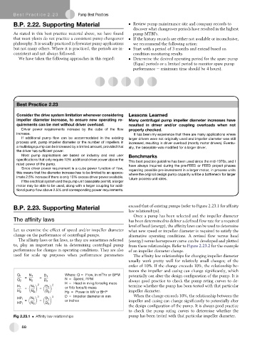
Where: Q = Flow, in m /hr or GPM
Q 1 N 1 D 1 potentially can alter the design configuration of the pump. It is
= = N = Speed, RPM
Q 2 N 2 D 2 always good practice to check the pump rating curves to de-
H = Head in m-kg force/kg mass
2 2 termine whether the pump has been tested with that particular
H 1 N 1 D 1 or ft-lb force/lb mass
= =
H 2 N 2 D 2 Hp = Power in kW or BHP impeller diameter.
3 3 D = Impeller diameter in mm When the change exceeds 10%, the relationship between the
HP 1 N 1 D 1
= = or inches impeller and casing can change significantly to potentially alter
HP 1 N 2 D 2
the design configuration of the pump. It is always good practice
to check the pump rating curves to determine whether the
Fig 2.23.1 Affinity law relationships pump has been tested with that particular impeller diameter.
88