
Page 111 - Subyek Teknik Mesin - Forsthoffers Best Practice Handbook for Rotating Machinery by William E Forsthoffer
P. 111
Be st Practice 2 .20 Pump Best Practices
Figures 2.20.21 and 2.20.22 present the guidelines for con-
firmation of excessive piping stress and/or soft foot.
Bearing (anti-friction)
P a r a m r e t e i L m s t i
Correcting excessive pipe stress and
Bearing housing vibration (peak) 10 mm/sec (.4 inch/sec)
Bearing housing temperature 85 C (185 F) foundation forces on equipment
Lube oil viscosity off spec 50%
Lube oil particle size Of all the different problems with rotating equipment, the
non metallic 25 Microns
resolution of excessive pipe stress is the most difficult. Why?
m c i l l a t e a n y m a g n c i t e p e l c i t r a n i h t e s u m p
Lube oil water content below 200 ppm Correction can involve extensive work that will require a sig-
nificant amount of safety permits and may even require pro-
cess unit shutdown. Figure 2.20.22 shows the suggested
Fig 2.20.17 Condition monitoring parameters and their alarm limits excessive pipe stress solution procedure. It is naturally
arranged in a cost-effective order (simplest, least costly action
first).
Correcting soft foot problems can be extremely simple if
Bearing (hydrodynamic)
equipment support feet are not level to the foundation. In this
P a r a m r e t e i L m s t i
case, stainless steel shims can be added. However, in some
Radial vibration (peak to peak) 60 microns (2.5 mils) cases, baseplates can become distorted and/or the foundation
Bearing pad temperature 108 C (220 F) can experience differential settlement over a period of
Radial shaft position* > 30 change and/or 30% position
change
Lube oil supply temperature 60 C (140 F)
Lube oil drain temperature 90 C (190 F)
Lube oil viscosity off spec 50%
Lube oil particle size > 25 microns
Lube oil water content below 200 ppm
*except for gearboxes where greater values are normal from
unloaded to loaded
Fig 2.20.18 Condition monitoring parameters and their alarm limits
More than one (1) bearing failure, rotor breakage, or coupling
failure per year
Unexplained high vibration (usually indicating misalignment)
Unexplained high bearing housing temperature
Pipe supports close to equipment not vibrating, equipment is
vibrating
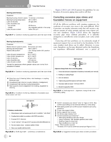
Fig 2.20.21 Shaft alignment e alignment change limits when
Fig 2.20.19 Condition monitoring indications of excessive pipe connecting piping
forces and/or soft foot
1
Confirm excessive pipe stress (refer to Figure 2.12.5). Also
confirm pipe bolting can be removed without a ‘come along’
Walk piping system and confirm proper installation per piping
isometrics
Proper pipe support shims
Spring supports free to move
No obvious pipe misalignment
Correct excessive pipe stress by: 2
Attempting rebolting at the next flange
Using ‘Dutchman’ with flexitallic gaskets (each side)
Heating of pipe for alignment
Pipe modification at next T&I
1
Notes: Work permits required
2 All items in III must be confirmed correct per Figure 2.12.5.
Fig 2.20.20 Shaft alignment e preliminary considerations Fig 2.20.22 Suggested excess pipe stress solution procedure
84