
Page 109 - Subyek Teknik Mesin - Forsthoffers Best Practice Handbook for Rotating Machinery by William E Forsthoffer
P. 109
Be st Practice 2 .20 Pump Best Practices
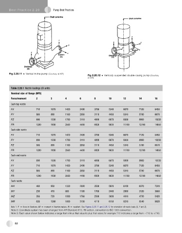
Fig 2.20.11 Vertical in-line pump (Courtesy of API)
Fig 2.20.12 Vertically suspended double-casing pump (Courtesy
of API)
Table 2.20.1 Nozzle loadings (SI units)
Nominal size of flange (NPS)
Force/moment 2 3 4 6 8 10 12 14 16
Each top nozzle
FX 710 1070 1420 2490 3780 5340 6670 7120 8450
FY 580 890 1160 2050 3110 4450 5340 5780 6670
FZ 890 1330 1780 3110 4890 6670 8000 8900 10230
FR 1280 1930 2560 4480 6920 9630 11700 12780 14850
Each side nozzle
FX 710 1070 1420 2490 3780 5340 6670 7120 8450
FY 890 1330 1780 3110 4890 6670 8000 8900 10230
FZ 580 890 1160 2050 3110 4450 5340 5780 6670
FR 1280 1930 2560 4480 6920 9630 11700 12780 14850
Each end nozzle
FX 890 1330 1780 3110 4890 6670 8000 8900 10230
FY 710 1070 1420 2490 3780 5340 6670 7120 8450
FZ 580 890 1160 2050 3110 4450 5340 5780 6670
FR 1280 1930 2560 4480 6920 9630 11700 12780 14850
Each nozzle
MX 460 950 1330 2300 3530 5020 6100 6370 7320
MY 230 470 680 1180 1760 2440 2980 3120 3660
MZ 350 720 1000 1760 2580 3800 4610 4750 5420
MR 620 1280 1800 3130 4710 6750 8210 8540 9820
Note 1: F [ force in Newtons; M [ moment in Newton meters; R [ resultant. See Figures 2.20.11 and 2.20.12 for orientation of nozzle loads (X, Y and Z).
Note 2: Coordinate system has been changed from API Standard 610, 7th edition, convention to ISO 1503 convention.
Note 3: Each value shown below indicates a range from minus that value to plus that value; for example 710 indicates a range from e710 to þ710.
82